This thread has been locked.

If you have a related question, please click the "Ask a related question" button in the top right corner. The newly created question will be automatically linked to this question.

OPA2277: OPA2277&OPA2192 Output characteristics

Part Number: OPA2277
Other Parts Discussed in Thread: OPA2192

Tool/software:

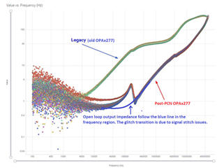
When an Nch-FET is connected to the output of an OPAMP (OPA2277, OPA2192), the Nch-FET may oscillate. OPA2277 may oscillate, but OPA2192 does not, so I am looking for data sheets or S-parameters that describe the output characteristics (impedance, capacitance, inductance) of OPA2277 and OPA2192.

  • Hi Koichi-san,

    OPA2277 may oscillate, but OPA2192 does not,

    The circuit description implies that both circuit may be V-I converter type. 

    OPA2277 has GBW near 1MHz while OPA2192 has GBW approx. 10MHz. These are two totally different amplifiers. You can not compare the performance of the op amps by generalizing the comparisons. 

    The op amp oscillation is related to additional pole presented in your circuit within a closed loop. Typically there is a resistor tied to the NMOS gate, and V-I circuit are sensitive to additional poles generated via Vgs and Vgd and overall phase lag in the feedback circuit. So the apple to orange comparisons are not applicable in this case. The AC loop analysis performance is needed in order to understand the difference. 

    If you are able to provide the schematic, I will be happy to analyze the circuit, and provide you the reasons about the root causes why one is oscillate (in OPA2277) and one is not in OPA2192.  

    If you have other questions, please let me know. 

    Best,

    Raymond

  • Thank you for your reply.
    Please let me know if there are any PCN notifications for factory changes or process changes for OPA2277UA between 2022 and 2025. Thank you in advance.

    Best regards.

  • Hi Koichi-san,

    any PCN notifications for factory changes or process changes for OPA2277UA between 2022 and 2025.

    Yes, OPA2277UA is issued the following PCN on 3/7/23. This implies that the current OPA2277UA is post-PCN Si design (likely, if the pre-PCN inventory is depleted.), and the output characteristics are slightly different from pre-PCN OPA2277UA product. 

    https://mm.digikey.com/Volume0/opasdata/d220001/medias/docus/5042/PCN20230228008.1.pdf

    All op amps are sensitive to drive capacitive load, weather or not is parasitic or actual capacitive load at output ( Cload value depends on the op amp's output characteristics). However, if the op amp is properly compensated, it will work fine for the application. 

    If you can show me the schematic, I can compensate the OPA2277UA's feedback loop for the V-I application. 

    If you have other questions, please let me know. 

    Best,

    Raymond

  • Thank you very much for sharing the PCN information.

    Please note that for confidentiality reasons, we cannot disclose the circuit diagram.

    Additionally, please allow me to confirm the following.

    -You said that the output characteristics after the PCN are slightly different from the OPA2277UA product before the PCN, but does that mean that the output impedance and reactance have changed?

    -Would it be possible for you to disclose the specific numerical values ​​that have changed?

    Best regards.

  • Hi Koichi-san,

    -Would it be possible for you to disclose the specific numerical values ​​that have changed?

    The main differences are reflected in the open-loop output impedance and UGBW (unity gain BW) of the new OPAx277 product. 

    The new FAB OPAx277 has lower open loop output impedance between 4kHz and 3MHz range, and UGBW is slight higher at approx. 2.5MHz. These are the difference. If the op amp's application is driving capacitive load, then you need to take care of additional poles near an UGBW per the circuit configuration. I am unable to comment since I do not have your schematic.  

    If you have other questions, please let me know. I am going to close this query. 

    Best,

    Raymond

  • Thank you for your reply. I cannot provide a circuit diagram, but there is an Nch-FET installed after the OPAMP and it was used to amplify DC voltage, but this Nch-FET was oscillating at high frequency due to the OPAMP difference. I can understand if the output impedance of the OPAMP differs due to the PCN difference. Thank you for providing the data.
    Best regards.