This thread has been locked.

If you have a related question, please click the "Ask a related question" button in the top right corner. The newly created question will be automatically linked to this question.

LMH6629: Gain and Phase Measurements of the TIA circuit

Part Number: LMH6629
Other Parts Discussed in Thread: LMH32401

Tool/software:

Hi,

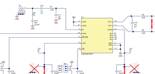
I have a TIA circuit with LMH6629 on a PCB. Now, I want to measure the TransImpedance gain and phase response of the TIA. I don't have an AC current source. BUT, I have AC Voltage source and VNA. How should I measure that? Thanks!

  • Hello Ratul,

      Thank you for reaching out. We have done similar setup in the lab without a photodiode or AC input current source. The method we use is highlighted below:

      This is from a PowerPoint with more details attached below. Make sure that C1 is your estimated photodiode capacitance you are planning to use, and then LMH6629 should be setup in a standard TIA configuration with the appropriate feedback capacitance for stability.

       We have developed a tool for designing TIA circuits with photodiodes. You can modify multiple input parameters like output voltage range, diode current, selection of opamp, etc. At the output you can see transient + frequency response, noise analysis, etc. If you want a starting point for Cf, please take a look at the TIA circuit design tool: Analog circuit design studiowhich will recommend a Cf (and also best op-amps) for the required circuit conditions. Also if your circuit is not following the minimum stable requirement, a warning will pop up in the bottom right window.

    3326.Transimpedance design flow using high speed op amps.pptx

    Thank you,

    Sima

  • Thanks! I don't have a photodiode for my applicaiton. In that case, what should be the C1 and C2 values? I have done TINA simulation of the circuit with LMH6629 with just an AC current source at the non inverting input.

  • Hello Ratul,

      Sorry for the delay in response. Are you going to be using a photodiode in the future? If not, I would set an example low input capacitance value of 1pF. But, would need to make sure CF is set to a value where (Cinput/Cf) + 1 > 4 since the device is only stable at gains greater or equal to 4V/V. 

      Here is an e2e thread on this same topic with more details. The links in the response do not work, but the summary I gave after the response is the same information: e2e.ti.com/.../opa818-testing-tia-without-photodiode

      Please feel free to ask any questions for more clarifications from above link.

       Also, as a simpler quick method, you can use the same values as below from LMH32401EVM, which shows how to test with a voltage source if no current source is available. The LMH32401 as integrated feedback capacitance to keep amplifier stable, this will need to be added for LMH6629.

    Thank you,

    Sima