This thread has been locked.

If you have a related question, please click the "Ask a related question" button in the top right corner. The newly created question will be automatically linked to this question.

TLV9102: Op-amp constant current source design feedback

Part Number: TLV9102


Tool/software:

Hello all,

I hope you're having a nice day.

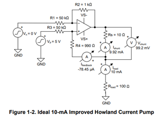
Lately I have been sketching this constant current circuit that uses the TLV 9102S, a dual operational amplifier. The idea is to supply a constant current (1 mA) through a resistive sensor connected between the CC source and ground. This should then allow the voltage across the sensor to be measured to calculate its resistance.

This is my current design. I built the circuit on a piece of breadboard and measured it with a desktop multimeter. The load resistor was a 1 kΩ, 1 % resistor. The circuit produced an average current of 994.031 µA (min/max 993.853/995.457 µA) into the load over a 15-minute data logging period. The peak in the beginning shows the moment when the 12 V power supply was turned on.

Now I would be interested to know if there are some ways to improve this basic design?

Thanks!

  • The image below shows the result measured without capacitors C42 & C44. The signal appears more noisy.

  • Hi Arttu,

    The idea is to supply a constant current (1 mA) through a resistive sensor connected between the CC source and ground.

    For 1mA  CC source, it will be easier to use the following topology. 

    https://www.ti.com/lit/an/sboa437a/sboa437a.pdf?ts=1740682041480

    https://www.ti.com/lit/an/snoa474a/snoa474a.pdf?ts=1740753042598&ref_url=https%253A%252F%252Fwww.ti.com%252Fproduct%252FLMV841

    Your approach will work, but it requires a lot more external components and typically it is used for higher output current that is unable to source/sink by the op amp. That is why BJT or Mosfet are used to boost the current rating. For 1mA, op amp can easily source/sink the amount of current. 

    I am going to close this query. You can still post the comments if you have additional questions. 

    Best,

    Raymond

  • Raymond,

    thank you for your information. I will check out and build a prototype of the circuit you linked and get back to you later next week.

    There's just one thing I'm concerned about the circuit in Figure 1-2. I am not sure how much current the "Vp" input will source/sink from the 4.096 V reference. Maybe the Vp input could be buffered with the first channel of the TLV9102S dual, while the second channel would act as a current pump.

  • Hi Arttu,

    I made up an example in Howland current pump and see if it helps. 

    TL9102 Howland Ipump 1mA 03032025.TSC

    Please let me know if you have other questions. 

    Best,

    Raymond

  • Hi Raymond

    Finally had some time for doing some testing with the current pump circuit you kindly provided.

    I had to do some modifications due to lack of 5k resistors. R2-5 had to be substituted by 5.6k resistors. Dual lab PSU provided both the 12 V supply and 4.096 V reference. I connected 0, 1, 2 and 3 470 ohm resistors in series with an ammeter (multimeter) to act as a load.

    Somehow I mistakenly read your "upper RL" value as 1k. With that value the circuit provided about 3.1-3.5 mA into the load depending on load resistance. Then I replaced the upper RL with series-connected 1.5k + 4.7k as I had these values at hand. In addition to the load current, I also measured the output voltages of each op-amp. The results were as follows.

    "Lower" RL "Upper" RL Iout Vout1 Vout2
    0 Ω 6.2 kΩ 607.3 µA 3.73 V 0.01 V
    470 Ω 6.2 kΩ 609.4 µA 4.02 V 0.29 V
    940 Ω 6.2 kΩ 611.6 µA 4.32 V 0.57 V
    1 410 Ω 6.2 kΩ 613.4 µA 4.62 V 0.86 V

    Current regulation was about 6 µA. It is almost exactly 1 %, which also happens to be the tolerance of the resistors I used in my test circuit. Do these results seem typical?

  • Hi Arttu, 

    Current regulation was about 6 µA. It is almost exactly 1 %, which also happens to be the tolerance of the resistors I used in my test circuit. Do these results seem typical?

    The Iconst_current is determined by Vref/RL resistor value. 

    If you want to have precision ±1mA with low %errors, you may need to consider Precision Op amps, which these have low Vos. You need to use precision matching feedback resistors as well (say ±1% or better) and RL resistor tolerance needs to be low, no greater than ±0.5% (prefer to have ±0.1%). Or you can parallel  two or more ±0.5% resistors together to lower the %errors. 

    You can improve the matching resistors first. If matching resistors do not meet your objectives, you may need to change to precision op amp. 

    This is Vos in TLV9102 op amp:

    For instance, if you use our precision series op amp + matching feedback resistor + other consideration (say use chopper amplifier), you should be able to get exceptional stable current source (assume your input Vref is stable over temperature and time).The precision op amp series will have Vos in 10uV or <  10s uV over temperature. 

    https://www.ti.com/amplifier-circuit/op-amps/precision/products.html#2max=0.01%3B0.025&sort=2max;asc&

    https://www.ti.com/lit/wp/sboa586/sboa586.pdf?ts=1741299600329&ref_url=https%253A%252F%252Fwww.google.com%252F

    If you have other questions, please let me know. 

    Best,

    Raymond