This thread has been locked.

If you have a related question, please click the "Ask a related question" button in the top right corner. The newly created question will be automatically linked to this question.

LM358: Generating Noise on O/P Side

Part Number: LM358

Tool/software:

Hello,

We have developed a metering application which use dc offset voltage to measure the ac voltage and current. 

SENSING CARD_V06.pdf

We have used LM358 to generate 1.65VDC Offset voltage and that voltage is provided to neutral terminal of 3phase voltage and current circuit. It is working as expected but it generates noise on output side and isolation issue when neutral is connected with main supply. 

I intend to validate that does this scheme will work.

Kindly validate the attached schematic and let us know if any modifications is needed on sensing section. 

  • Hi Nilesh, 

    but it generates noise on output side and isolation issue when neutral is connected with main supply. 

    In 3-phase system, the neutral terminal should have voltage near zero, if the AC winding is balanced. The noises likely come from the 3-phase; you may minimize the noises by coupling a capacitor between Neutral terminal to Earth GND. I am not sure that LM358 is able to withstand the transient voltage at the Neutral terminal for the application. For high voltage transient events at neutral terminal, LM358 op amp may not be able to survive the voltage variation at the node (over temperature and time). What is the application?

    What does it mean when Neutral terminal is connected to main supply. Please clarify. 

    We have developed a metering application which use dc offset voltage to measure the ac voltage and current. 

    What is the total system power in the application? Typically, AC voltage is measured via voltage divider using differential circuit and AC current is measured via current sensing transformer, shunt resistor or Hall effect sensor. Is this a motor application?

    Best.

    Raymond

  • Hello,

    FYI, this circuit is designed for metering application for measuring three phase voltage and current.

    We took reference of the meters which used the same topology, and it is working as expected. However, it is generating noise in our design.

    The main functionality of an op-amp in design is to generate offset voltage and sum that voltage to ac voltage divider circuit.

    I am assuming that this issue has happing because of the two different grounding of SMPS circuit. GND and GND_ISO. Does it could generate the noise?

  • Hi Nilesh,

    I am assuming that this issue has happing because of the two different grounding of SMPS circuit. GND and GND_ISO. Does it could generate the noise?

    You did not mention if the 3-phase is motor or transformer. The neutral connection can be any potential it wants to be. If all the phase and load are balanced, the neutral terminal should be close to GND. For transformer, the neutral terminal can not be DC biased, since it may saturate the magnetic core of the transformer. 

    Did you tie a capacitor to Earth_GND? The common-mode noise at neutral terminal provides a discharge path to ground via the capacitor, which acts as a low impedance path and shunt noise to Earth_GND (high frequency noise filter). What types of noise are you able to observe in your design?

    Please let me know if you have questions. 

    Best,

    Raymond

  • Hi Nilesh,

    I am going to close this query, since I have not heard from you. 

    If you have other questions, please let us know. 

    Best,

    Raymond

    HVA Application Team

  • Nothing is connected with 3phase like motor or transformer. It is 3phase voltage measurement circuit. 

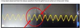
    I am going to attach the output of op-amp which is measured at R_Phase side which is connected with microcontroller.

    Kindly find it and let me share the resolution.METER_PROBLEM_DISCUSSION.pdf

  • Hi Nilesh, 

    In 3-phase system, the Neutral phase should have 0 AC voltage and current if the 3-phase is in a balance system. 

    3-phase AC 03122025.TSC

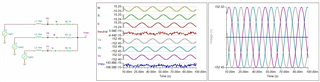
    In an unbalanced 3-phase system, the magnitudes of the phase voltages are not equal. As a result, the vector sum of the phase voltages will not be zero, which can lead to a non-zero neutral voltage and current. This is what you observed from the scope shot. 

    Here is another likely possibility as well. What type of scope probe do you use? You need to get a probe without the long flexible GND return leads. Probe the signal next to a GND signal in your measurement. And these spikes will be likely gone. 

    The voltage spikes near the peaks and valleys are resulted from Ldi/dt events in your unbalanced 3-phase system. It is not from the op amps. 

    If you have other questions, please let me know. 

    Best,

    Raymond

  • Thanks for response.

    I would like to inform you that we have the same meter which is the reference meter which is working as expected without any noise with the same supply. Why are these noises not observed with it?

  • Hi Nilesh, 

    we have the same meter which is the reference meter which is working as expected without any noise with the same supply.

    In the reference meter circuit, you can replace the circuit with the same op amp in LM358, and you should found that the issues are not caused by the op a amp. 

    Why are these noises not observed with it?

    Please compare your 3-phase impedances with the reference meter. You can measure it with LCR meter vs. reference meter, and hope that you will find a difference. If you have other questions, please let me know. 

    Best,

    Raymond

  • I want to know that how much voltage should apply on VCC pin of Op-amp if i want to get 3V on Output side?

    I have provided 3.3V on VCC; However, 5V is provided on VCC in reference meter.

    Does it may create an issue?

    Moreover, Where I can measure the 3-phase impedances?   Can you share the procedures?

  • Hi Nilesh, 

    I want to know that how much voltage should apply on VCC pin of Op-amp if i want to get 3V on Output side?
    I have provided 3.3V on VCC; However, 5V is provided on VCC in reference meter.

    Yes, this could be part of your problem, see the Vcm requirements and op amp's output droop in this part. 

    For LM358, if you want to get out of 3Vdc at the output, the op amp's supply voltage has to above 7-8Vdc with some design margin (assume single supply rail configuration). The input Vcm has some limit and output voltage has some droop, depending on the output current. Prefer to use 10 or 12V LDO with low ripple voltage.  

    Moreover, Where I can measure the 3-phase impedances?   Can you share the procedures?

    If you have LCR meter, you need to configure and match the frequency range or close to it and compare the inductance figures. 

    Can you send me a picture of your 3-phase setup? I am not able to picture what you have in your configuration. 

    Best,

    Raymond

  • Hello,

    I have provided 5V supply to op-amp's VCC. But the problem remained same.

    Can you review our layout?

    It would be very helpful for resolving the issue. 

  • Hello, 

    Could you send me the schematic? So far, we have exchange multiple replies, but I have no ideas how you setup the op amp. 

    Best,

    Raymond

  • Hello,

    I have already sent you the schematic. 

    For more analyses, kindly review the Gerber files and let me know your comments.

    Seansing Gbr_v06.zip

  • Hi Nilesh, 

    My mistakes that I did not remember that you did send the schematic from the get-go. 

    Here is my speculation. From your LM358, the output is tied to the Neutral in your system,. The noise spikes can come from the voltage divider as well as 3.3Vdc supply. The 3.3Vdc comes from LDO (AMS117), the PSRR in the LDO is around 60-76dB at 120Hz. It does not attenuate the noise well when we are dealing with 10kHz or more. Assume -20dB/decade filter, at approx. 10kHz, the PSSR is left approx. 20dB range. If the 3.3Vdc ripple noise is high, it will show up at the output of op amp.  

    At 78M05 regulator, the PSRR looks better than AM117 3.3Vdc LDO. The plot is captured from TI's part, but I do not know what you are using. 

    https://www.ti.com/lit/ds/symlink/lm341.pdf

     I am also found that your LC filter may have Q in the frequency response, if it is operating in voltage mode. I lowered the Q slightly, but you have to use larger capacitor value (and low ESR) if you want to deQue the circuit, typical is 5X of 100uF or more. You may also use snubber circuit to dampen the Q. This may bee another source of spikes that you are observing. 

    I will take a look at Gerber file when I got a chance. But this is what I am thinking of, if you have taken care of potential probing issues at the output of the LM358. 

    Best,

    Raymond

  • Hello,

    I made the circuit on the breadboard which is providing the output as expected.

    However, In designed PCB, I am getting the noise.

    Please review the attached Gerber and let me know if any modifications is needed.

  • Hi Nilesh, 

    It is good to see that you are making progress. Please modify the existing PCB circuit and see if you can improve the performance. 

    When dealing with switching power supplies, you need to keep the noise down. For general purpose op amp application, the supply rail's voltage ripple needs to be in approx. 10mVpk or better range. In precision op amp application, the supply rail's voltage ripple needs to be kept below 1mVpp. 

    I will take a look at the Gerber file when I got chance. It has been really busy in our application support team lately. 

    Best,

    Raymond