XTR117: XTR117 (0-10V to 4-20mA)

Part Number: XTR117
Other Parts Discussed in Thread: XTR111

Tool/software:

Hey,
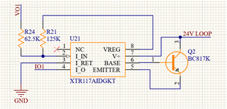
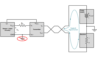
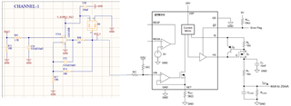
I have tested this circuit on a sample 2-layer PCB and verified that everything is properly connected to the XTR IC. However, after making all the connections, the IC is heating up excessively. I am unable to debug the issue and determine the cause.

Currently, the circuit includes a BC817K transistor, but I also have an MMBTA28-7-F, which can be used as an alternative.
VO1 is coming from the another board which is generating the 0-10V signal, on same board we have analog current input circuit where IO1 is connected. 
From same board we have provided the 24V loop and IRET Gnd connection. 


  • Hi Dheeraj,

    I have a few questions: 

    • Is the device heating excessively when it's not outputting a current?
    • How hot is the device reaching? 
    • IRET GND is actual ground or the local ground? 
    • Is the output 0-10V signal accurate during the test? 

    Best Regards,

    Robert Clifton

    • Yes, it is heating excessively. I didn't check the output; I just turned off the circuit. It heated the PCB board significantly—way more than normal.

    • IRET is the ground connected from my other board, and it is the actual ground.

    • The output is stable as we are generating it from the analog voltage output port from my other board via STM DAC.

  • Hi Dheeraj,

    IRET is the ground connected from my other board, and it is the actual ground.

    I'm not sure that this is related to the thermal heating problem but I do want to address this. IRET should only be a local ground for the input and should not be connected to the actual ground. I highly recommend watching the TI Precision Labs Video: Current loop transmitters: Basic design considerations that will go in more detail but the IRET ground needs to be floating from the actual ground since it will vary across different input signals. 

    Here's a few schematics to help with how it should be designed in relation to the input circuitry. 

    Let's fix this and see if that also corrects the thermal heating of the device. 

    Best Regards,

    Robert Clifton 

  • So should I leave it floating? Iret pin and test the circuit. 

  • Hi Dheeraj,

    No it's still the return path for the input signal. What is generating the input signal to your XTR117? 

    Best Regards,

    Robert Clifton 

  • As I mentioned in my previous post, the 0-10V signal is generated by another board, which is connected to this XTR117 circuit. In that board, the 0-10V signal is generated by an STM microcontroller along with other circuitry.

  • Hi Dheeraj,

    I knew your circuit looked familiar. I went back to our original thread (XTR117: XTR117 (0-10V to 4-20mA)) and checked back through the suggestions I gave. 

    One big thing I pointed out was the concern of the transistor. I forgot to ask you this time if the transistor you are using is also heating up to very hot levels? 

    In that board, the 0-10V signal is generated by an STM microcontroller along with other circuitry.

    What is this other circuitry that is generating the 0-10V signal? Would you be able to share the schematic of the other board? Or at least the relevant subcircuits regarding the input and output of the XTR117? That might make this easier for us to diagnose.

    Best Regards,

    Robert Clifton 

  • Hey Robert, Transistor is not heating up. XTR IC is heating up. 
    Also 0-10V signal is very stable we are using that in our stable product. Which provide signal to actuator like devices. 
    Attached 0-10V Circuit. AVO is analog voltage output that is connected with external port. DAC is going to STM. 

  • Hi Dheeraj,

    Give me some time as I try to piece these two schematics together.

    Best Regards,

    Robert Clifton

  • Hi Dheeraj,

    Just to confirm, AVO_1 or AVO_2 goes to the VO1 on the XTR117 board? 

    You mentioned that the 0-10V is stable. I'm not concerned about that. I'm curious if the output of the XTR117 is also outputting the expected values. If you are able to, can you get a reading of what the current is when you apply 0V on the input. Then I'd like to see what the output current is at 10V. 

    If they aren't matching up then the error is likely coming from the IRET path being tied to ground. 

    Best Regards, 

    Robert Clifton 

  • Hey Robert, I will check the values. But if IRET is not tied to ground, where should I connect it? Because locally or originally, that's the only ground reference I have.
    Yes AVO1 going to XTR117. 24V loop is also coming from same board. 

  • Hey Robert, I have checked at 0-5-10V but current is always 0. 

  • The XTR117 must be used in a two-wire system.

    In a three-wire system, use a three-wire transmitter like the XTR111.

  • Hi Dheeraj,

    But if IRET is not tied to ground, where should I connect it? Because locally or originally, that's the only ground reference I have.

    There's a few weird things about two-wire systems. First, and the most obvious one is with two wires, the output wires are receiving the supply voltage that powers the 4-20mA current loop and also has the load as shown below. Also because the supply is being powered by the loop, you have to make sure that the transmitter, sensor, and input circuitry must consume less than 4mA. 

    Second, and this is where the confusion is coming from, IRET is not the system ground. See the image. 

    Now the video I linked here TI Precision Labs Video: Current loop transmitters: Basic design considerations goes into why in more detail but here's the derivation screenshots: 

    When outputting 4mA VIRET relationship to ground is about 1.1V

    When outputting 20mA, VIRET = 5.5V to ground. 

    The voltage on IRET needs to not be tied to ground. It's still the return for the signal so it needs to tie the signal input circuitry to it as I've shown before here:

    Here's a few schematics to help with how it should be designed in relation to the input circuitry. 

    The return current loops are critical for two-wire devices in ways that aren't in three-wire devices. 

    As Clemens mentioned it looks like your circuit might be more in line with using a three-wire device rather than a two-wire. Just for reference here's a simplified difference between these two types of 4-20mA systems.

    Best Regards,

    Robert Clifton

  • Thanks Robert
    I got the point. Now, what changes do I need to make in my circuit for it to work?

    Can you please elaborate with respect to my circuit? Where should different wires be connected to my other board?

  • Hi Dheeraj,

    I think changing the XTR117 to be a 3-wire XTR111 is the first step. My rough drawing of how it should be connected to your board is shown below if you go this route. Please not this is not a complete circuit, as I'm missing the VREG section. 

    Let me know if this helps.

    Best Regards,

    Robert Clifton