This thread has been locked.

If you have a related question, please click the "Ask a related question" button in the top right corner. The newly created question will be automatically linked to this question.

THP210: Interfacing THP210DR with AMC1200

Part Number: THP210
Other Parts Discussed in Thread: AMC1200, AMC1300

Tool/software:

Hello All,

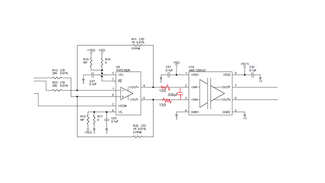
We have design where we are sending differential voltages from a DAC to a THP210 and also have an isolation amplifier (AMC1200) after the THP210 to isolate the noise from the digital side. At the output side of the AMC1200 the differential voltage from the AMC1200 is converted to single ended voltage which eventually serves as the programming voltage of a current source. As you can see from the following schematic that currently the THP210 outputs are directly connected to the AMC1200 inputs and we have ran into issues, such as, the AMC1200 providing more than expected voltages at its output, and when the differential voltage is at max the voltages at the output of the THP210 and AMC1200 are not steady, voltage values jumps around quite a bit. So, we are adding a filter network just before the AMC1200, the filter consists of two 12ohm resistors on each of the input lines and a 330pF capacitor between the two input pins. My question is- will the THP210 be stable with this new filter circuit added?

Your insights are much appreciated. Thank you.

  • Hi Roy,

    My question is- will the THP210 be stable with this new filter circuit added?

    Yes, it should be stable, maybe I will perform loop analysis to verify the stability. 

    when the differential voltage is at max the voltages at the output of the THP210 and AMC1200 are not steady, voltage values jumps around quite a bit.

    When THP210 outputs the differential voltage, what is the max. amplitude of the signal. The AMC1200 has differential input limits up to ±250mV. If the peak to peak signal exceeds the limit, then it may not operate it properly. Please clarify. 

    the filter consists of two 12ohm resistors on each of the input lines and a 330pF capacitor between the two input pins

    This LPF is to address the differential input noise. Do you see the improvement if the above differential LPF is implemented? I'd like to know that the observed fluctuation at the output AMC1200 is common or differential noises. AMC1200 seems to have pretty good CMRR up to 50kHz. Do you use switching power supply to provide ±15Vdc at THP210 or 5Vdc at AMC1200?

    If you have other questions, please let me know. 

    Best,

    Raymond

  • Hi Raymond, thanks for your reply.


    When THP210 outputs the differential voltage, what is the max

    The max differential input voltage to the AMC1200 is +200mV, and -215mV. 

    Do you see the improvement if the above differential LPF is implemented?

    Yes, actually I do see some improvement. After the said filter was implemented, at max positive differential voltage to the AMC the voltages are not shifting around anymore. 

    Do you use switching power supply to provide ±15Vdc at THP210 or 5Vdc at AMC1200?

    The THP210 and AMC1200 are both powered from same the 5V rail. The 5V rail is generated (from a higher voltage source) via a combination of switch mode and linear power supply.

  • Hi Roy, 

    You need to modify the circuit in order to be stable. As simulated, the phase margin is approx. 180-132.14 = 47.9 degree (differential gain is low). 

    The differential LPF has the cutoff frequency at approx. 169kHz. If this is low, please let me know. I do not know what application this is. 

    THP210 Loop Analysis 03052025.TSC

    The 5V rail is generated (from a higher voltage source) via a combination of switch mode and linear power supply.
    at max positive differential voltage to the AMC the voltages are not shifting around anymore. 

    My speculation is that the switching power supply did not have low LPF filter, say the switching power supply's frequency components near 50kHz or higher. Most LDO does not have adequate or poor PSRR against higher switching or higher frequency noise. The differential noises may be coupled into the THP210 and AMC1200, and resulted the bouncing signal at the AMC1200's output. 

    In THP210, if the high frequency components below 10kHz, PSRR should be 90dB or better. If switching noises are beyond 100kHz, the rejection is getting poorer. Similar is true for AMC1200. 

    Please let me know if the solution will work for you. 

    Best,

    Raymond

  • Hi, 

    The equivalent input resistance of the AMC1200 IC is 28k. My concern is if I increase the filter resistors (100 ohms in your suggestion) there might be considerable drop across them due to current flowing from THP210 outputs to AMC1200 inputs. If I do not add any filters at all would that be Ok, stability wise. FYI, this is a DC application meaning only DC voltages will be applied at the inputs.

    Thanks.

  • Hi Roy, 

    If I do not add any filters at all would that be Ok, stability wise.

    Yes. Without 4.7nF, the THP210 should be stable, however, the circuit may increase broadband noise slightly without the 16.9kHz differential LPF at the output. 

    If you limiting the BW of THP210 by paralleling a capacitor with feedback resistor 1kΩ (both feedback side), that may work as well or close to be equivalent with differential LPF. 

    If you have other questions, please let me know. 

    Best,

    Raymond

  • Hi Raymond,

    I am thinking to take up your suggestion and add the filter (consisting of two 100 ohm resistor, ad 4.7nF differential cap) you suggested between THP210 and AMC1200. But the AMC1200 datasheet suggests we use a value less than 24 ohm for the filter resistors as you can seen from the underlined text (from section 8.2.1.2, page 16) in the AMC1200 datasheet. Apparently, using a value higher than 24 ohm might result in incomplete settling of the AMC1200 input circuitry. Will it be safe to add the 100 ohm resistors then considering AMC1200 input settling? 

    Thank you.

  • Hi Roy, 

    Will it be safe to add the 100 ohm resistors then considering AMC1200 input settling? 

    I think that this is the question for AMC1200 team. That 8.2.1 section is written for motor control application and it may be intended to filter output high EMI noise, PWM switching noises, common-mode noise, Ground noise etc. from motor applications. 

    I will transfer you to AMC1200 team. 

    Best,

    Raymond

  • Hi Roy,

    AMC1200 has a switched cap input as described in the input filter section of the datasheet and what you underlined. With a high resistance, less current can flow into the charge bucket cap and therefor incomplete settling can be achieved. 

    I do not see an issue with trying the 100ohm resistors and checking for performance from your side. It will depend on your application requirements. 

    You could also consider an alternative device such as AMC1300 that has integrated FDA if this is an issue.