This thread has been locked.

If you have a related question, please click the "Ask a related question" button in the top right corner. The newly created question will be automatically linked to this question.

THS4531: Glitching observed at -40 C ambient

Part Number: THS4531


Tool/software:

To whom it may concern,


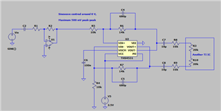
We have implemented the THS4531 in the following single-ended to differential configuration, ensuring that none of the parameters specified in the datasheet have been violated.


However, we have seen glitching on the output at -40 C ambient.  An example of the glitching has been captured on the following scope trace:


This glitching is still present even with input reduced to no signal at all and seems to disappear altogether when warmed up.


It should also be noted that only around 15 % of the boards produced with this circuit seem to exhibit this issue.


Do you see any reason for the chip to behave this way in the above configuration? Also, we would appreciate if you could suggest a solution that does not involve a major design change as this circuit is used in a currently shipping product.


Look forward to hearing from you.


Many Thanks,

Bhav

  • Hello Bhav,

    I can help investigate this behavior with you.

    My first request would be to see if a known good unit exhibits the glitch on a 'known issue' board; similarly if a 'known issue' IC exhibits no issue on a 'known good' board.  This A-B swap would help understand if rework/handling and IC/board variance are to be considered.

    15% is a fairly high rate for a non-ideal behavior to occur; could you share any layout or PCB files?  I can message you privately on e2e to exchange emails if you prefer.

    My first thought would be if there has been any issues with storage/moisture for the units?  Older units or units which have had exposure to moisture can exhibit odd behavior at the temperature extremes (for operating temperature).  

    Whatever the cause may be, I think we need more information to help out.  If you can check the A-B-A swap and also work with me on more design details (like PCB), we can progress on resolving this behavior.  If needed, we can consider additional options for official return, good-faith shipment to TI (my office) for debug, and debug/analysis via email/exchange of information.

    I will also check across my team to see if any cold temp glitches are known about for either this device family or the process technology.

    Best,

    Alec

  • Hi Alec,

    Thank you for your prompt response.


    Have you had any feedback from your team regarding cold temperature glitching? Have any of your customers experienced this before?

    Regarding sharing the layout, we are discussing it internally and we will confirm as soon as we get authorisation to share.

    Since my initial post, we have tried the following (all tested as per original schematic, unless otherwise stated):

    1. Removed output connection to 'another TI IC' and substituted it with 40 k differential resistor - No improvement

    2. Removed feedback capacitors - Glitching disappeared

    3. Changed the supply to +/- 2.5 V - No improvement

    4. Probing single-endedly with a standard 10 x passive probe directly on input or output pins - Glitching disappears

    5. Adding 22 pF in parallel with R4 - Glitching disappeared

    Look forward to hearing from you.

    Many Thanks,

    Bhav

  • Hello Bhav,

    Thank you for the update.

    Do you see the glitching if you proportionally reduce RF and RG resistors (14k and 10k respectively) to keep same gain configuration?  Sometimes in FDA circuit the high resistor values can increase noise contributions and effects.

    You do not need to do this if you need these specific values for any filtering, but for now I just observe a typical FDA configuration with feedback capacitors.

    It is interesting adding 22pF in parallel with R4 removed the glitch; this is effectively decoupling higher frequency noise.  What are the target frequencies of operation for this design? 

    Best,

    Alec

  • Hi Alec,

    Thanks for your speedy response.

    We have not tried reducing RF and RG resistor yet, but will do.

    This in an audio application and this stage requires a ~16 kHz cut-off frequency.

    One thing we noticed when cooling the part is the drop in output common-mode from 1.25 V to ~0.9 V.  Is this what you would expect to see?

    Many Thanks,

    Bhav

  • Hello Bhav,

    The data point of output common-mode voltage changing over temp is good to know.  I will check with the team on this, but it would be expected for VOCM to stay at the level set by the VOCM pin, due to the internal output common mode buffer.

    Can you confirm the IQ of the FDA at cold temp?  I also wonder if the output load remains consistent over temperature.

    Regarding your debug step #4 above: when you probe each output there is no glitch, how are you measuring the FDA outputs when you do observe the glitch?

    Best,

    Alec

  • Hello Alec, I work with Bhav who is on vacation today. As this problem is quite serious and we are on ship hold, I wanted to answer your questions now and not wait till next week.

    1. As we use power planes, we are not able to measure IQ without lifting the power pin. We were concerned that this would them change the chip behaviour. We can measure IQ it it will help you get an answer.
    2. The probing is done after the 16k resistors. Apologies we should have explained that. We have disconnected the other TI chip and used an equivalent load resistor, but see no difference in the behaviour, so do not suspect the other TI chip to be cause of the problem.
    3. We definitely see the "output" common mode change with temperature. It is ~1.25 V at room temperature and dips down to 0.9 V at cold and then recovers, ie back to 1.25 V at the temperature is increased back to ambient. The VOCM pin remains at 1.25 V. Looks like the common mode voltage control inside the chip is temperature dependent.

    Please let us know if we can provide any other information.

    Thanking you for your continued support

    Dipak

  • Hi Alec,

    One correction to the information above;

    The VOCM input and Output Common-mode does not change with cold temperature and remains at 1.25 V.

    The observation of the ~0.3 V shift was isolated to a single-board and could not be seen on the few others we've since tested.

    Any initial thoughts from you or your team?

    Many Thanks,

    Bhav

  • Hello Bhav,

    Thank you for the update.  It is good to confirm VOCM input and output common mode voltage do not deviate from 1.25V.

    Initial thought: the THS4531 outputs may be oscillating/unstable due to driving the output capacitors.  The stability issue may only present itself at cold temperatures.

    A way to check this would be to add small series resistance at the outputs of the FDA, providing isolation resistance between the output impedance of the FDA and the capacitors.  This resistance could be in a range as described in Section 9.2.8 Driving Capacitive Loads in the THS4531 datasheet.

    You could also check this by removing the capacitive loading if you are unable to add small series output (isolation) resistors at OUT+ and OUT-.  When you probe the device pins directly and notice the glitch disappear, the inductance of the probe may be offsetting the load capacitance and changing the amplifier's stability.

    Best,

    Alec

  • Hello Bhav,

    I also have some more feedback after discussing with my team:

    1. This could be a stability issue where the Cfb (feedback capacitors) change the Aol and reduce the stability of the amplifier at cold temp.  The removal of Cfb fixes the glitch, which supports this idea.  The amplifier may be slamming high to handle the instability and then recovers.

    2. A fix for this would be to remove Cfb and not filter in the feedback loop.  Instead, you could use a parallel output capacitor to add filtering to the THS4531 outputs prior to the inputs of the next TI device.

    3. Overall you can reduce the resistance of Rf (and adjust Rg accordingly), as the 14kOhm Rf value is high and will contribute to noise and offset terms.

    You can implement the 16kHz audio cutoff frequency with a passive output filter to eliminate the effects of Cfb on the stability of the FDA.  You can also adjust Rf values and tune the circuit to be more stable at cold temperatures.  

    As I recognize you may not be able to add a capacitor to the output of the THS4531 to make a passive filter w/ R8 and R9, you can also reduce the Cfb capacitance.  A lower capacitance will have less of an effect on stability.  You can adjust Cfb, Rf, and Rg to tune for better cold temp behavior.  Based on the 15% observance rate, this behavior is tied to stability and the circuit design likely has the potential to be instable at cold temp, as it is not happening to every circuit board.

    Best,

    Alec