Other Parts Discussed in Thread: ISO1541
Tool/software:
I am using INA3221 in schematic to monitor the voltage and current with a negative power supply. I will use digital isolator between INA3221 and MCU.
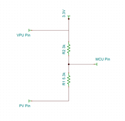
I am wondering about Vpu (16) pin of the INA3221. How do I connect it ?
I already connected Vs (4) pin to PCB Ground and the GND (3) pin of INA3221 is connected to -5 V in my schematic.
I think I need to connect a resistor between Vpu (16) pin and Vs (4). The Vs (4) is already connected to PCB Ground at 0 potential.