Dear Sir,
I would like to know the basic steps to test RLD circuit.
I have no idea how to start? Please kindly help me?
Best regards,
Enid Juan
This thread has been locked.
If you have a related question, please click the "Ask a related question" button in the top right corner. The newly created question will be automatically linked to this question.
Dear Sir,
I would like to know the basic steps to test RLD circuit.
I have no idea how to start? Please kindly help me?
Best regards,
Enid Juan
RLD circuit means right leg driven circuit which is usually attached to Rg of instrument amplifier. ^^
Hi Enid,
The purpose of a Right Leg Drive circuit is to improve CMRR by biasing the body with a known potential that is related to the the common-mode inputs of the signal chain. So you could test your RLD circuit to see if common-mode signal rejection is improved when using the RLD with a ECG simulator versus the results when not using the RLD circuit.
Here is a good application note on right leg drive amplifiers:
http://www.ti.com/lit/an/sbaa188/sbaa188.pdf
Table 1 shows the results when using the RLD feedback vs. no RLD.
Regards,
Collin Wells
Precision Linear
Dear Sir,
Thank you for answering. I have read this PDF file earlier and want to know how to simulate RLD circuit with TINA .
Would you please help me??
Best regards,
Enid Juan
Hi Enid,
Figure 5 shows an example RLD circuit, build this circuit up to see what kind of output the RLD circuit will have. TINA has an abundance of application circuits that you can start with and modify if you're having trouble figuring out the basics of the program.
Best Regards,
Collin Wells
Precision Linear
Dear Sir
Thank you for your quickly replying. ^^
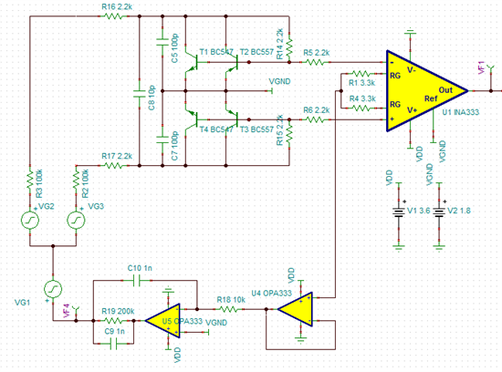
Actually, I did some design work about RLD circuit. (see the figure below)
I just don't know how to test this circuit.
How should I choose noise source? or the following steps....
That would be great help for me.
Thank you very much~
Enid

Hi Enid,
I understand your question now, sorry for the confusion. I do not know how to run the tests you're referring to. One of my colleagues that used to work with our group does though and I will contact him today.
In the mean time I would take a look at the U5 circuit, it looks like an integrator circuit with a few strange extra components and doesn't look like a standard RLD circuit.
I will be in contact soon.
Best Regards,
Collin Wells
Precision Linear
Agreed. That guy could probably solve global warming and green energy as well if you gave him enough time.
Enid,
I was not able to dig up the information I was looking for today. I will continue looking tomorrow.
Best Regards,
Collin Wells
Precision Linear
Enid,
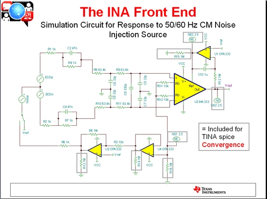
I was able to find what I was looking for. Here are a few slides from a presentation from my colleague. The first is an example ECG acquisition circuit. Items contained in the grey boxes are required for proper SPICE convergence.

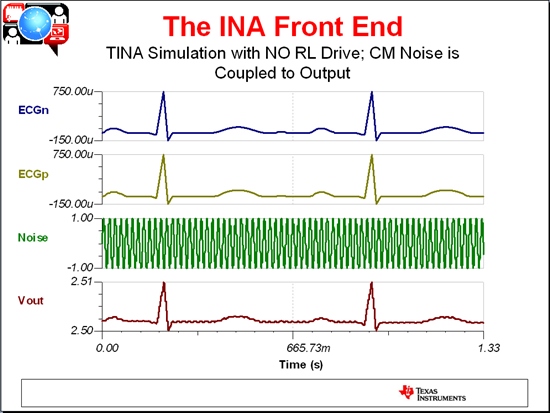
Results with the switch set to "VREF" not using the RLD Output:
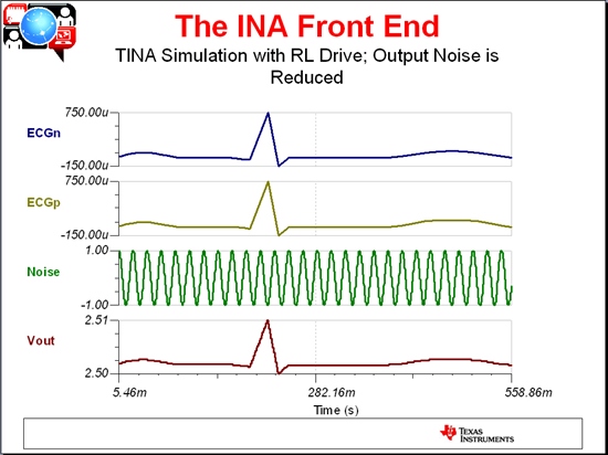
Switch set to use the RLD Output:
I hope this helps.
Best Regards,
Collin Wells
Precision Linear