This thread has been locked.

If you have a related question, please click the "Ask a related question" button in the top right corner. The newly created question will be automatically linked to this question.

INA180-Q1: EOS Broken

Part Number: INA180-Q1
Other Parts Discussed in Thread: INA240

Tool/software:

Hi Teams,

Customers have used the INA180-Q1, but IN+ PIN is broken. Check to see if the negative pressure of the input is the cause.

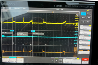
This is the wave. Yellow is SP_L, Blue is SN_L and Orange is PN.
This is the Sch.
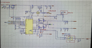
Please help to analysis the reasons as soon as possible.

This is BYD SOP Zone control project. So it is very urgent.

Thank you!

BRs,

Ruoxin

  • Voltages that exceed the absolute maximum ratings can indeed damage the device, especially if they happen repeatedly.

    There are some spikes visible in the waveform, but they are harmless (> −300 mV). I guess they can be larger? Is it possible that the line is being touched (resulting in ESD), or do all spikes come from the load switching?

    The IN pins have clamping diodes to GND that cannot tolerate more than 5 mA. You can increase robustness by adding external (Schottky) diodes in parallel. A small resistor (< 10 Ω) between the external diode and the pin ensures that most of the current flows through the external diode; consider increasing Rg7/Rg9.

  • Hi Ruoxin,

    As Clemens has pointed out, if your pulse waveform's spikes exceed the abs max ratings then you will damage the ESD diodes in the device. I agree with Clemens' suggestions to improve your schematic. However, if your signal has significant switching, I'd recommend a part with PWM rejection like the INA240/INA241.

    Best,
    Mallika Senthil