This thread has been locked.

If you have a related question, please click the "Ask a related question" button in the top right corner. The newly created question will be automatically linked to this question.

OPA350: Measured output is double simulated (expected) output level - Pt2

Part Number: OPA350
Other Parts Discussed in Thread: OPA1632

Tool/software:

Hi again,   and . I am finally back on to trying to debug this board with the OPA350. See original thread you were helping me on "Measured output is double simulated (expected) output level".

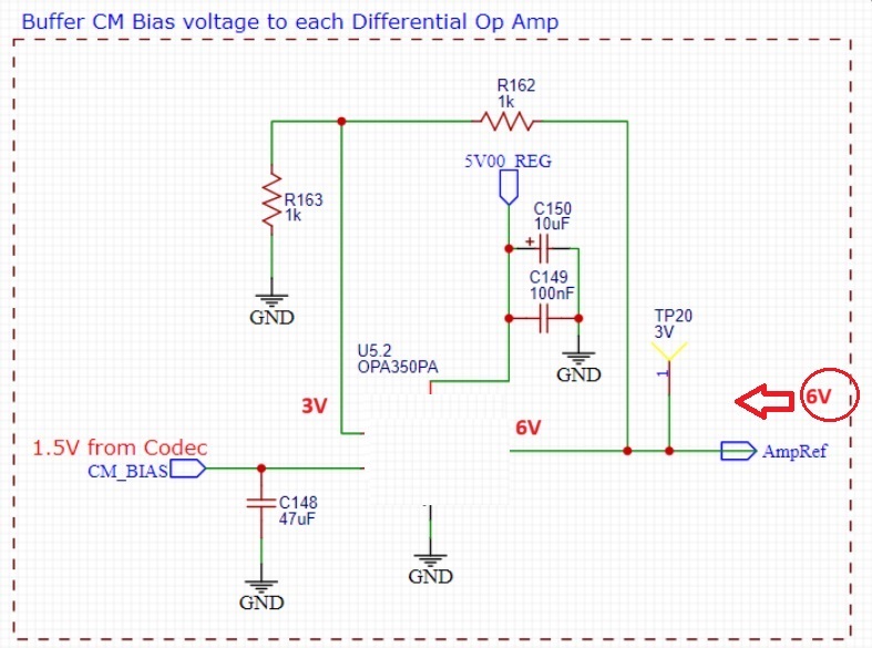
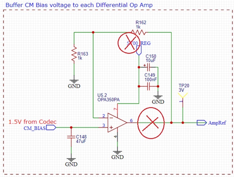
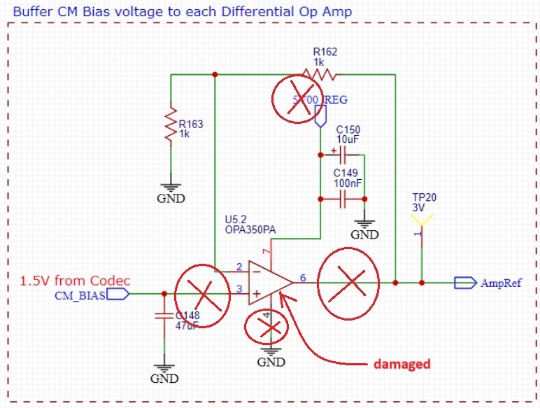
As requested, I have removed the OPA350 and I measure 6V DC on TP20 (which should be ~ 3V DC).

For completeness:

OPA350 voltage readings at each pin:

pin 2: 3.0 V

pin 3: 1.5 V

Pin 4:  0.0 V

Pin 6:  6.0 V

Pin 7: 4.9 V

Other test point voltages:
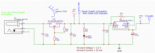
TP3:  12V

TP5: 3.2 V

TP10:  0 V

TP19: 3.2 V

TP18: 4.9 V

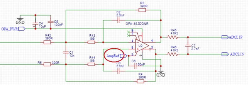
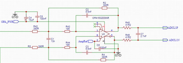
Voltages on OPA1632 pins:

pin1: 6.1 V

Pin2: 6.1 V

pin3: 12 V

pin4: 6.1 V

pin5: 6.1 V

pin6: 0 V

pin7 12 V

pin8: 6.1 V

pin 7 is supposed to be not connected (refer below schematic)

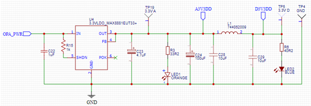
And other parts of the power supply portion of my schematic, and repeating the path to my APO1632's:

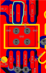
demonstrating pin 7 of OPA1632 on PCB layer

Any tips on how I can narrow down this problem with the above supplied information now?  Many thanks!

Mark

  • Marek will be back this week and I have assigned to him since he is more familiar with your application.

    Please give him a couple days to respond.

    Thanks for your patience and your post.

    Chuck

  • Mark,

    Sorry for the delay, the post assignment didn't happen correctly.

    The reason output is always 6V is because that node is being forced to 6V by something more powerful than the op amp. 

  • Hi , yes, I understand this and it is addressed in my first thread that I refer to here in this post.  I am hoping for some response/guidance to the question I have posted here, in particular the voltage on pin 7 as I am seeking assistance to solve this problem.  Perhaps can pick this up as he was addressing this for me in my original thread?!

    Thanks for your assistance.

    Kind regards,

    Mark

  • Mark.

    I reassigned Marek Lis to help you. 

  • Mark,

    The fact that after removal of OPA350 you still see at the output 6V should not come as a surprise when you consider that AmpRef is connected to Vocm (pin 2). 

    When there is no external driver for Vocm (pin 2), OPA1632 Vocm is driven by the internal voltage divider to mid-supply. 

    Below please find the OPA1632 functional block diagram showing Vocm being driven to 6V with supply voltage (V+) of 12V - see below.

    All in all, the most likely reason why you see AmpRef (Vocm) at 6V instead of 3V is a faulty connection of OPA350 supply voltage or its output pin - see below.

  • Thanks , this is really helping me understand where to look for the problem.  I've gone and looked at all the connection pins of all my connected OPA1632's. I found some interesting results when assessing resistance of each pin (using 200 kΩ setting on my DMM). For completeness I provide the measurement results of each pin of each connected OPA1632 with "suss" connections in red text for your comment (Op-amp identifier numbers match those in my schematic):

    Output stage OPA1632 op-amps: 

    U2:

    Pin 1:  ∞ Ω

    Pin 2:  0.7 kΩ

    Pin 3:  0.7 kΩ

    Pin 4:  ∞ Ω

    Pin 5:  ∞ Ω

    Pin 6:  0.0 kΩ

    Pin 7:  51.9 kΩ

    Pin 8:  ∞ Ω


    U3:

    Pin 1:  ∞ Ω

    Pin 2:  0.7 kΩ

    Pin 3:  0.7 kΩ

    Pin 4:  ∞ Ω

    Pin 5:  ∞ Ω

    Pin 6:  0.0 kΩ

    Pin 7:  51 kΩ

    Pin 8:  ∞ Ω

    Pin for pin readings seem equivalent between U2 & U3.


    Input stage OPA1632 op-amps: 

    U8:

    Pin 1:  ∞ Ω

    Pin 2:  0.7 kΩ

    Pin 3:  0.7 kΩ

    Pin 4:  ∞ Ω

    Pin 5:  ∞ Ω

    Pin 6:  0.0 kΩ

    Pin 7:  51.9 kΩ

    Pin 8:  ∞ Ω


    U11:

    Pin 1:  ∞ Ω

    Pin 2:  0.6 kΩ

    Pin 3:  0.7 kΩ

    Pin 4:  ∞ Ω

    Pin 5:  ∞ Ω

    Pin 6:  0.0 kΩ

    Pin 7:  0.0 kΩ

    Pin 8:  ∞ Ω


    U12:

    Pin 1:  0.7 kΩ

    Pin 2:  0.7 kΩ

    Pin 3:  0.7 kΩ

    Pin 4:  0.7 kΩ

    Pin 5:  15.5 kΩ

    Pin 6:  0.0 kΩ

    Pin 7:  15.7 kΩ

    Pin 8:  15.7 kΩ


    U13:

    Pin 1:  ∞ Ω

    Pin 2:  0.7 kΩ

    Pin 3:  0.7 kΩ

    Pin 4:  ∞ Ω

    Pin 5:  ∞ Ω

    Pin 6:  0.0 kΩ

    Pin 7:  50.2 kΩ

    Pin 8:  ∞ Ω

    Pin for pin readings seem equivalent between U2, U3, U8 & U13.  Op-amps U11 and U12 have questionable results. Can you provide some comments as to where I should go next with this?  Could one of these be causing my problem?

    Kind regards.

    Mark

  • Mark,

    The only explenation for why OPA350 is NOT able to drive AmpRef to 3V is that its output is in a high impedance state.  This is only possible if:

    1. OPA350 is damaged

    2. a bad connection between pin 6 and AmpRef

    3. a bad connection between 5V supply and pin 7

    4. a bad connection between CM_BIAS and pin 2

    5. a bad connection between ground and pin 4

    Thus, do not look anywhere else since the problem is only around OPA350.

  • Thanks .  Since my OPA350's are thru-hole's I'll replace it and re-test just to rule out damaged device.  In point 4 above, did you mean: "a bad connection between CM_BIAS and pin 3"?

    Also, when you say "a bad connection", can you provide me some more information about what you mean by this and what I should test for to prove this "bad connection"?

    Many thanks!

  • sorry for the delay

    I believe Marek was referring to having a cold solder joint (not good connection)

    Chuck

  • Yes. i meant a bad connection between CM_BIAS and pin 3.  A bad connection may be caused by any number of things:

    - cold solder joint 

    - frayed or exposed wires causing unintended shorts

    - loose connections

    corroded connections or insulation

    - faulty switches, etc,