This thread has been locked.

If you have a related question, please click the "Ask a related question" button in the top right corner. The newly created question will be automatically linked to this question.

LOG200: Log Ratio Amplifier

Part Number: LOG200
Other Parts Discussed in Thread: LOG114, INA849

Tool/software:

Hi there,

I have a quick question surrounding log ratio amplification using the LOG200, details given below.

Best regards,

Tim

Background

Our application requires high bandwidth measurement of two photodiodes.

The older LOG114 was designed with this in mind, since it offered essentially identical performance on either input.

I understand that the LOG200 has input asymmetry; one high accuracy input and one high bandwidth input. However, I would like to make use of the increased bandwidth, adaptive biasing, and improved log conformity when compared to the LOG114.
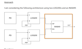
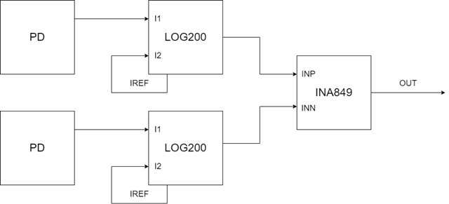
Approach

I am considering the following architecture using two LOG200s and an INA849:

Questions

Is this likely to yield better performance than a single LOG114?

Do you think there is a better suited approach?

  • Hi Tim,

    I have a few questions: 

    Can you share the input current range that is expected from the PD? 

    What is the target performance in your system? 

    Best Regards, 

    Robert Clifton

  • Thanks for your reply, Rob.

    Since this is an early-stage research project, the input current range is currently unknown.
    For now, let's assume that the signals of interest will be in the nA to µA range.

    Here is some background on why this is hard to determine at present.
    We will be stimulating a sample with a laser.
    Photodiode 1 is used to measure the transmission through the sample (at the stimulation wavelength).
    Photodiode 2 measures photoluminescence of the sample (at a different wavelength).
    The efficiency of transmission and photoluminescence are highly process-dependent and currently unknown.

    The PD currents will be periodically pulsed with t_{ON} ~ 1-5 us, thus requiring a high bandwidth. The idea is to use the log ratio of the transmission and photoluminescence to normalise variations in stimulation power. It is the signals during t_{ON} that are of interest.

    The target metrics are miniaturisation and high bandwidth sensitivity.

    I am sorry for my lack of quantitative information at this point.

    Regards,

    Tim

  • Hi Tim,

    It's quite alright. I appreciate you providing everything you have. 

    As of right now I think the proposal you have suggested could work. Depending on what you need to do, the LOG200 internal axillary amplifiers for you might be able to change the back end of the INA to a difference amplifier. It's too early to know for sure if that's the best method but you have options. 

    LOG200 will have a better response time compared to LOG114. With pulses, step response specs is likely critical. 

    Best Regards,

    Robert Clifton

  • What benefits would there be in using the auxiliary amplifiers as diffamps? I was considering using them as unity-gain LPFs, or, leaving them NC.

  • Hi Tim, 

    I support our INA portfolio so I can provide some more insight here. I believe Robert's comment was referring to the INA849 that you have after the LOG200 blocks (see image below). The auxiliary amplifiers in the LOG200 can be used as unity-gain low pass filters (that you mentioned earlier) or additional gain stages depending on what voltage range you need for the next stage (typically an ADC). We have a few schematic examples that show best practices for the LOG200 for photodiode current measurements in this application note that I recommend to reference: Perform Accurate Optical Current Sense Measurements Using the LOG200 Logarithmic Amplifier

    I have a few questions regarding this block, if you have this information available: 

    • Is the INA849 intended to have a gain? Or will it be used in unity-gain? 
    • Is the goal to compare the two photodiode currents with the INA block? 
    • What will the INA output be fed into? An ADC? 

    Please let me know if you have any questions.
    Thank you!

    Regards,
    Ashley

  • Hi Ashley,

    Thanks for your input. I have already read that Application Note but will reference it again as the design progresses. In response to your questions:

    • I intend to use the maximum gain on the INA849 which does not violate my bandwidth requirement
    • Yes, the goal is to compare the photodiode currents (removing the common-mode signal in some sense)
    • The INA output is likely to drive additional analog circuits; e.g. lock-in amplifier or an integrator before the ADC
      • These analog circuits aim to reduce the required sampling rate and noise

    Please let me know if you have any suggestions around this.

    Regards,

    Tim

  • Hi Tim, 

    Thank you for the additional information. I've outlined two circuit alternatives to consider as the design progresses. Once you have more details on the signal values and design parameters, please let us know as this will help us better understand your solution to provide more detailed suggestions. The below is generalized and with the information we have above. 

    Do you know what the expected differential signal will be from the photodiodes? The differential and common mode voltages, based on the input ranges of the photodiode, will help to determine what signal conditioning parts will be necessary for the signal chain and where in the signal chain you can compare the photodiode currents.

    I do not believe it will be necessary to add the additional analog circuits before the ADC other than potentially discrete filtering for the ADC, depending on which ADC you plan to use. 

    I have included both an INA and difference amp as options for the second scenario as depending on the necessary gain you need for the ADC range, either could work. 

    Please let me know if you have any questions.
    Thank you!

    Regards,
    Ashley