Part Number: LMP2011
Other Parts Discussed in Thread: MSPM0G1105, LMP2021, TINA-TI
Tool/software:
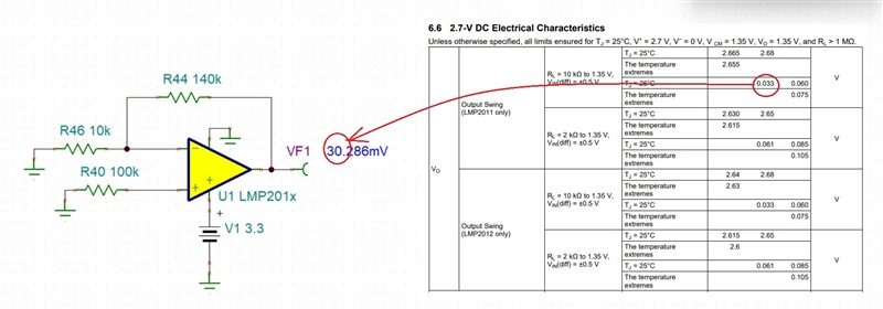
I'm using an LMP2011.
Even when I connect the input to ground, it still outputs about 10mV.
Please tell me how to correct the offset.
Thank you.
Hiroshi Yamada