Part Number: INA101
Other Parts Discussed in Thread: INA149, INA848, RES60A-Q1
Tool/software:
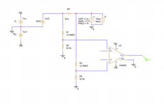
I want to design a current amplifier for measuring current through motors buy using shunts
the motors are DC
AC 3 phase motor
AC Pwm motors
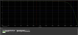
frequency 0-300k
current 0-5A
voltage between lines can reach up too 680v AC
output of amplifier 0-+- 10v
can be also an amplifier with supply voltage of one polarity better 2 polarities