This thread has been locked.

If you have a related question, please click the "Ask a related question" button in the top right corner. The newly created question will be automatically linked to this question.

BOOSTXL-3PHGANINV: Motor Control Parameter Calculation

Part Number: BOOSTXL-3PHGANINV
Other Parts Discussed in Thread: TINA-TI

Tool/software:

Hi,

I'm planning to use a custom motor driver board, and I need to modify some of the parameters in the "user_mtr1.h" file. I'm currently studying how these parameters are calculated for the BOOSTXL-3PHGANINV board.

Inside the SDK, there's a file named "Motor_Control_Parameter_Calculation.xlsx", and in that file, I noticed that the cutoff frequency of the LPF at the MCU's ADC input is calculated.

In the code, the resulting value is written as:

#define USER_M1_VOLTAGE_FILTER_POLE_Hz (1103.026917f)

However, the details of the calculation and the source of certain values are not entirely clear to me.

Specifically:

  • What is the source of the values in cells F21 and F22?

  • Also, why are the 100 kΩ and 4.22 kΩ resistors treated as if they are in parallel in the calculation?


Thanks,
Burak

  • Hi,

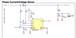
    Those two cells refer to this part of the schematic:

    There is a mismatch in the resistor cell however, it should have been 20 instead of 50. The frequency number increases slightly to 1111 when the correction is made.

    From the ADC input pin looking toward phase node, the equivalent resistance seen is Rs (20 ohm) plus the parallel combination of 100k and 4.22k. I think this is where the parallel calculation comes from.

    Regards

    Guang

  • Hi Guang,

    Thank you for the clarification regarding the resistor value.

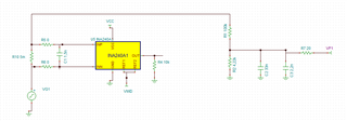
    I created the circuit in TINA-TI and ran an AC analysis simulation to observe the frequency response. Interestingly, the maximum gain is not close to 0 dB, and the response doesn't resemble that of a typical low-pass filter. I'm wondering if I might have made a mistake in the circuit setup.


    Best regards,
    Burak

  • Hi Burak,

    No you did not make a circuit mistake.

    Bode plot is showing the voltage gain from VG1 to VF1, which is 0.0405 or -28dB. The plot is correct.

    Regards

    Guang