This thread has been locked.

If you have a related question, please click the "Ask a related question" button in the top right corner. The newly created question will be automatically linked to this question.

XTR115: Digital Potentiometer used to control 4-20mA output to sensors

Part Number: XTR115
Other Parts Discussed in Thread: XTR111, DAC084S085, XTR116

Tool/software:

Hello, 

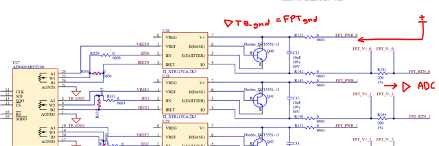
I am using the XTR115 along with a 100k digital potentiometer as shown in the following schematic: 


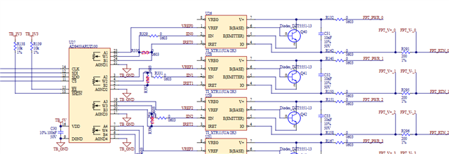
I am having a lot of issues with debugging this circuit, however. As is, I notice that the Vref voltage is quite low and Vreg is quite high. I believe the ESD protection circuit in the digital potentiometer is sinking the current and dropping the voltage of the floating XTR115. Only when I ground Iret to my test board ground does Vref = 2.5V and Vreg = 5V. I also replaced the R339 with a 40k resistor and was able to output a current/vary the voltage going into Iin. However, the current is far too small for the desired 4-20mA range (2.5/40k = about 6mA). I also considered powering removing the Vref connection and powering from an external source but that similarly had issues. What am I missing here? Why is Vref + Vreg dropping? Why is there a 1V+ potential between Iret and my TB_GND? Are there any simple solutions to fix my circuit? Do I need to swap out the 100k pot for something smaller to get the desired range? Any advice would be most welcome.  

Also, I isolated both and confirmed that both the digital pot and the XTR115 were working correctly independently. Only once they are implemented as above do these issues occur. 

  • The XTR115 is a two-wire transmitter, i.e., it expects the entire transmitter circuit to be powered from the loop, and that IRET is used as the floating ground for the sensing circuit.

    You probably need a three-wire transmitter like the XTR111. (Alternatively, build a constant-current source with a single opamp. A DAC like the DAC084S085 would be easier to use than a digipot.)

    Why are there separate power connections for each loop? Do you need level shifting? What is the architecture of your system?

  • The FPT_PWR0-3 are from an external device I’m trying to inject the 4-20mA into. Each of these are for the various sensors this device would normally connect to. This same device is tied to my TB_gnd through a jumper. No level shifting is needed. Everything is fine logic-wise and I’ve been talking to and changing these pots fine. 

  • Hi Michael,

    Clemens explanation is on point. IRET must be isolated from ground in 2-wire current transmitters. 

    I'd like to add onto Clemens comments. When you are running a system with multiple 2-wire configurations, you have to take into account that the Iret paths can't connect to each other nor ground. The pictures I will show later come directly from the TI Precision Labs: Current Loop Transmitters: Basic Design Consideration video. I highly recommend watching to get a more detailed analysis of what I'm about to explain. 

    Iret shouldn't be tied to ground in 2-wire transmitters as it's voltage relative to ground is going to shift depending on what the output current needs are.

    The same logic can be applied when you tie multiple Irets together. When they are outputting different currents, their Irets are going to be at different voltage potentials relative to each other as seen below: 

    To solve this, you need to isolate the input Iret paths from each other. Here we show two different circuits, both with valid ways of isolating the Iret path through the use of an ISO7330. 

    The problem I see in your design is that the AD8403 datasheet states that all AGND pins must be connected to DGND, which violates both rules of not tying the Iret together or ground. This circuit cannot be used directly connected to the inputs of a 2-wire current transmitter. Not unless you added an analog isolator after the potentiometer. 

    The alternative solution that Clemens presented of using a 3-wire transmitter like the XTR111 would also work, depending on your system's needs of course. 

    Let me know if you need any additional clarification or assistance. 

    Best Regards,

    Robert Clifton 

  • That makes a lot of sense to explain why Iret was a higher potential than TB_gnd. I'm still a bit uncertain why I saw Vreg and Vref drop when I attached them to the digipot circuit. 

    Given I would need to isolate the grounds, is it not possible to vary the resistance between Vref and Iret (if these are connected between a potentiometer) and leave that floating for all of the multiple 2-wire configurations? That was essentially the design plan for my circuit -  


  • If I wanted to amend my current design without having to redesign the digital potentiometer, what IC's from TI could I use? Any with the same package as the XTR115 haha? 

    I was thinking a voltage follower amplifier circuit might work or something to increase the current by a gain of about 100 (in this case the voltage). Any suggestions would be great 

  • Hi Michael, 

    I'm glad you replied because I was looking back at my answer and your original post and, while I explained the Iret and Ground differences, I felt that didn't cover the entire answer. I want to apologize for that. 

    That makes a lot of sense to explain why Iret was a higher potential than TB_gnd. I'm still a bit uncertain why I saw Vreg and Vref drop when I attached them to the digipot circuit. 

    When you took the Vref and Vreg measurements were you measuring the voltage between Vref and Iret or did you measure Vref to ground? Same for Vreg?

    Iret is the ground path for the Vref and Vreg. Those voltages will maintain their voltage potentials with Iret and hold no relation to any other grounds. 

    If I wanted to amend my current design without having to redesign the digital potentiometer, what IC's from TI could I use? Any with the same package as the XTR115 haha? 

    They all have such unique pin outs and packages unfortunately. 4-20 current transmitters aren't the same as the op amp industry where things are mostly standardized. The only other one that holds the same pinout and package is the XTR116.

    Given I would need to isolate the grounds, is it not possible to vary the resistance between Vref and Iret (if these are connected between a potentiometer) and leave that floating for all of the multiple 2-wire configurations? That was essentially the design plan for my circuit -  

    I do have concerns about the TB_GND and FPT_GND being tied together. It's all about the ground current loops with the 2-wire current transmitters. By tying those together you are creating another current path which could distort the signal. 

    This is a bit unrelated but what is the supply voltage of FPT_PWR? 

    Best Regards, 

    Robert Clifton