This thread has been locked.

If you have a related question, please click the "Ask a related question" button in the top right corner. The newly created question will be automatically linked to this question.

XTR115: xtr115 with DAC8741H

Part Number: XTR115
Other Parts Discussed in Thread: DAC8741H, SN74LVC1G373, DAC8742H, DAC8742HEVM, TIDA-01504, AFE881H1, AFE882H1

Tool/software:

HI 

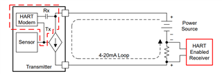
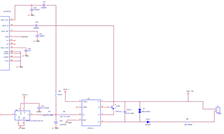
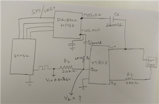
Can we interface DAC8741H with XTR115.Can you please explain how will this circuit works when interconnected

sreekar

  • The XTR115 cannot supply more than 3.75 mA, so you will not be able to power the measurement circuit, i.e., this is not possible. The DAC8741H datasheet shows an example circuit with a separate power supply.

  • Hi Clemens, 

    I'm not seeing where the DAC8741H would consume more than even 1mA of current. In fact this is based on a TI Design that mentions that the total current budget for this system is 2.6mA. 

    Best Regards,

    Robert Clifton 

  • Hi Sreekar,

    There's two ways that the DAC8741H could interface with the 4-20mA current loop. The Transmitter side and the Receiver side. 

    I'll talk about the transmitter side since that one is likely what you are talking about.

    We have a lot of great reference designs like the Highly Accurate, Loop-Powered, 4- to 20-mA Field Transmitter With HART Modem Reference Design. While it's discrete, how the DAC8741H interacts with the XTR115 would be similar. The DAC8741H would be connected to the LOOP+  and the input to the XTR115.

    One important thing to remember is that Iret would be connecting all of the "ground points" in the system shown in the reference design example. However you will not tie Iret to ground or you'd violate the floating ground point that all 2-wire 4-20mA current loops would need to operate properly. 

    Also all of the input devices should be less than the 3.75mA of current consumed, as Clemens said, in order to be able to have a proper output. 

    Let me know if you have any additional questions. 

    Best Regards,

    Robert Clifton

  • Hi Robert 

    Thanks for you quick reply. I have gone through the design TIDA01504.

    Implemented my design in this way. Can you please update if any changes need to be implemented in below circuit .It will be very much helpful.

    My entire ckt  current consumption is less than 3.5mA

    Regards

    Sreekar

  • Hi Sreekar,

    I found another E2E forum post that asks a similar question: https://e2e.ti.com/support/data-converters-group/data-converters/f/data-converters-forum/1412216/dac8740h-dac8740h-compatibility-with-the-xtr115 

    I have a few comments/questions

    First the bypass capacitor that was chosen on the output is too high for HART communication. You will need to lower it. Here's the recommendations in the datasheet. 

    What is the SN74LVC1G373 is for? 

    What is the expected input current range? 

    The absolute maximum power supply for the XTR115 is 40V but operating is 36V. I'd double check the TVS diode meets that criteria across all the expected temperature ranges that this system will operate in. 

    Best Regards,

    Robert Clifton 

  • Hi Robert

    I have implemented bypass capacitor change in my design from 22nf to 2nf.To eliminate noise

    I have a small quarry there is a series resistor of 49.9k when we calculate RMS value of both ac and dc current we are getting 499k.

    can you please suggest which resistor should we implement

    What is the SN74LVC1G373 is for?

    We are using it for pwm signal input from mcu.It will act as latch.

    Regards

    Sreekar

  • Hi sreekar,

    What is the SN74LVC1G373 is for?

    What is the SN74LVC1G373 being used for is what I meant to ask. Sorry for the confusion. 

    can you please suggest which resistor should we implement

    We might want to move this thread to the team that's responsible for the DAC8741H for a more detailed answer. Is there a reason that the 499kohm is a cause of concern? 

    Best Regards,

    Robert Clifton

  • Hi Robert

    I want to implement my design in this way.

    Can you please explain me in detail how can DAC8742 is used for calibration.

    Can we use DAC8742 for calibration?.And explain me in detail what does MOD_OUT Pin & MOD_IN Pin working.

    This is where i got struck in my design.Please help me out.

    Regards

    Sreekar

  • Hi Robert

    Can you please suggest which application software can be used to calibrate filed device(xtr115+mcu).With dac8742.

    Which drivers can be used.

    Regards

    Sreekar

  • Hi Sreekar,

    I'm going to move this thread over to the DAC team responsible for the DAC8742 as they are the subject matter experts.

    Best Regards,

    Robert Clifton

  • Sreekar,


    I generally handle questions on the DAC8742H.

    It looks like the device you're building is a field transmitter. Generally, I think this is how the devices would be connected to work together. In your schematic, you have the STM32 microcontroller, and then an XTR115 current loop transmitter.

    The DAC8742H is a HART modem and translates the HART bit communication into UART or SPI. It does not understand the HART protocol, but only translates from one set of bits to another set of bits. The DAC8742H has a MOD_IN pin which capacitively couples to the positive supply and senses the HART communication, and then it has a MOD_OUT pin that sends a ±500mV signal that would be converted to current in the loop through the XTR115.

    Now, what do you mean by calibration? The DAC8742H modem does not interpret the HART commands. It takes the HART signal and converts it into bits. The HART commands would be interpreted by the microcontroller, which would respond to the HART commands and send a response back to the DAC8742H. This firmware written to interpret the HART commands is known as a HART stack. Because of this there isn't any specific application software for this type of circuit. We do have a DAC8742HEVM, but this is only for the DAC8742H, and does not interpret any of the HART protocol.

    You can find the DAC8742HEVM here:

    https://www.ti.com/tool/DAC8742HEVM

    Just so you have some information about HART, here is a guide to the HART protocol:

    https://www.ti.com/lit/pdf/slaaeh0

    I think you have a good TI design reference in TIDA-01504, but here are a couple of application notes for some newer devices. Again, I think you have the right application note for the DAC8742H, but these notes have more of a discussion on some of the HART testing required.

    https://www.ti.com/lit/pdf/slaaeh8

    https://www.ti.com/lit/pdf/slaaer4

    Again, these notes are for some newer HART modem devices (AFE881H1 and AFE882H1). I pointed them out to show the HART testing aspect of these systems.


    Joseph Wu