This thread has been locked.

If you have a related question, please click the "Ask a related question" button in the top right corner. The newly created question will be automatically linked to this question.

TLV3601: Long delay when used as current zero crossing detector with a shunt resistor

Part Number: TLV3601
Other Parts Discussed in Thread: TLV3511, INA185

Tool/software:

Hi,

I am trying to design a current zero crossing detector with TLV3601 based on the following circuit:
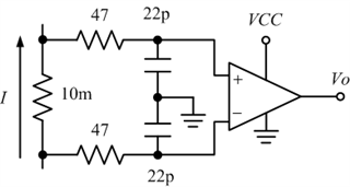
However, I found that there is a long delay (~150 nS) between actual current zero crossing and TLV3601 output change, much longer that datasheet specifications.

What can I do to minimize this delay?I need the delay to be <40 nS, preferably <10 nS. I have tried using smaller RC values for the LFP before TLV3601, but it did not help

I noticed that the delay specified in comparator datasheets are usually based on an overdrive voltage of 50 or 100mV, while I may want my comparator to respond at <1 mV input voltage difference. Is this the reason why I am getting much longer than datasheet specified delay?

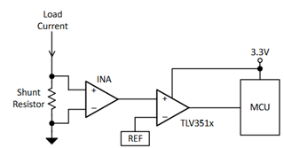
Is there any comparator that can meet my delay and input voltage requirements? Or will it help if I add a preamplifier stage, similar to the following schematic from TLV3511 datasheet? If yes, which amplifier should I choose? The TLV3511 datasheet does not seems to provide any recommendations for the INA.
Thank you

  • Hi Hsin-Che,

    What's the current swing across the 10mΩ shunt resistor? What's the frequency of your tests? Could you please share some oscilloscope shots of the observed delay?

    I noticed that the delay specified in comparator datasheets are usually based on an overdrive voltage of 50 or 100mV, while I may want my comparator to respond at <1 mV input voltage difference. Is this the reason why I am getting much longer than datasheet specified delay?

    Yes, comparator propagation delay is a function of both overdrive and underdrive. Comparators generally get slower with a small overdrive and a large underdrive.

    Two things of note that may be delaying the propagation delay of the comparator:

    1. An input differential swing of +/- 1mV is too low. The typical offset of the TLV3601 is +/- 0.5mV. This means that the input differential will need to exceed the offset voltage before the input signal even begins to propagate to the output of the comparator.

    2. TLV3601 has 3mV typical of internal hysteresis. With a small input swing, this hysteresis that is meant to prevent chattering of the output may be suppressing your input signal. The effect would be similar to point 1, where it "delays" the switching of the comparator.

    Is the purpose of the LPF at the inputs to suppress high frequency noise? The LPF adds a delay element which slows down the overall propagation delay; you can try to see if you can remove the LPF and see if the internal hysteresis is enough to prevent chattering at the comparator output.

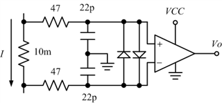
  • My schematic actually look like this. I forgot to show the clamping diodes in the previous schematic.

    I have tried to reduce the two 47-Ohm resistors, replace the two 22-pF capacitor with resistor or remove the clamping didoes. However, nothing seems to noticeably shorten the delay time. One thing I have noticed is that if I remove the diodes, there is a lot of false triggering at lower current.

    The current I am trying to sense is an asymmetrical sawtooth. It can go up to ~10 A in the positive half cycle and 1-2 A in the negative half cycle. Frequency is variable, around 50-500 kHz.

  • Hi Hsin-Che,

    there is a lot of false triggering at lower current.

    Just to clarify, lower current as in low current magnitude or the negative half cycle (-1A to -2A)? False triggering at low current magnitude can occur since the low differential makes it so that noise or interference can cause chattering at the output of the comparator.

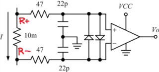
    I was under the impression that the TLV3601 circuit was the same as the TLV3511 low-side current sensing circuit as shown, but I just noticed that the TLV3601 circuit provided has no information on the nodes. What's the VCC of your TLV3601 circuit? What are the voltages at nodes R+ and R-?

    Is there any way you can share some scope shots of the observed delay? Are you probing from IN+ to IN- of the TLV3601?

  • The current I am sensing is an asymmetrical sawtooth wave. The negative half cycle can range between -1A to -2A. The positive half cycle can range between 1 to 10A.  The VCC for TLV3601 is 3.3V.

    The false triggering is at lower current magnitude (~+-1A or less).

    Sorry, I am not able to capture any waveforms at this point. The experimental setup is taken apart right now. I was measuring the output of TLV3601 and comparing it with input current.

    I expect the comparator to change state when the voltage drop between R+ and R- is ~1mV or less. Now I understand that the built-in hysteresis might prevent this and that's why I my TLV3601 change state long after zero crossing.

    Maybe I am doing this all wrong, choosing the unsuitable part or circuit configuration. If you were to design a high speed and precision current zero crossing detector, what part(s) and circuit configuration would you choose?

    Thank you

  • Hi Hsin-Che,

    The current swing and subsequently voltage swing being 1mV is too low since it's within the range of the input referred offset of most comparators. You'll need to increase the voltage swing somehow, either by increasing the shunt resistor to a larger value (increasing V/I conversion but increasing power dissipated across resistor) or amplifying the voltage with a current sense amplifier like in the TLV3511 figure.

  • Considering the power loss and thermal issue of using a higher shunt resistance, I guess my only choice would be adding a preamplifier before the comparator.

    Do you have any recommended part number for this preamplifier?  Obviously the input to output propagation delay of this preamplifier would contribute to the total delay. However, datasheets of most op-amps does not seems to provide this information, only slew rate and bandwidth.

  • Hi Hsin-che,

    I'm not too qualified to make suggestions for current sense amplifiers as those products are handled by another group. Could you please make an additional post asking for device suggestions? A good place to start could be the INA185, a fixed gain current sense amplifier.