This thread has been locked.

If you have a related question, please click the "Ask a related question" button in the top right corner. The newly created question will be automatically linked to this question.

PGA849: 'Gain vs Frequency' graph on datasheet does not match simulation

Part Number: PGA849
Other Parts Discussed in Thread: TINA-TI, ,

Tool/software:

Hello TI,

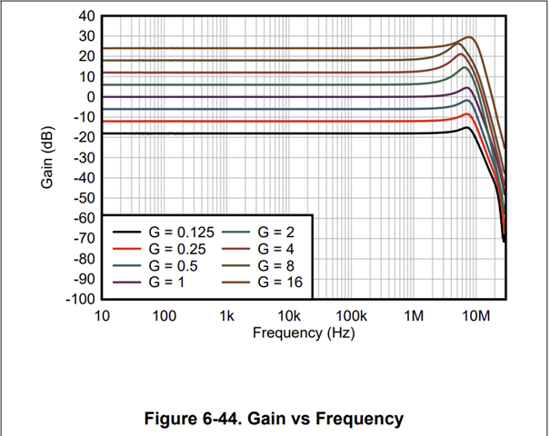
I downloaded the PGA849 TINA-TI Reference Design directly from the TI website. However, after running an AC analysis, I noticed the resultant 'Gain vs Frequency' graph does not match what is shown on the datasheet. In simulation at G = 1, the -3dB point occurs at approximately 12.3Mhz, and no peaking is visible. I adjusted the values to match the parameters listed on the datasheet, but the response is the same.

I have also purchased the PGA849EVM, and the frequency response aligns more closely with the simulation.

Is there a specific configuration required to replicate the results seen on the datasheet?

Thank you for your time,

SK

  • Hello SK, 

    Welcome to e2e :) 

    For the simulation, it looks like the simulation model's bandwidth is wrong for gains 2, 4, 8, and 16 (measuring at 5MHz). For gains below 1 (inclusive), the bandwidth is within the typical range ±30%, looks consistently high at ~12MHz. I have reported this to our simulation engineers so it may be fixed across all gains. 

    For the datasheet - this is the golden source, since bandwidth is a typical value, some variation can be expected across process and lots - industry standard ±30%. I looked at the characterization data for the device and the bandwidth across gains is 10 MHz.  

    Gain (V/V) Bandwidth (MHz)
    0.125 9.99
    0.25 10.13
    0.5 10.24
    1 10.32
    2 10.41
    4 10.1
    8 9.52
    16 11.7

    In practice, it is good to have more than 10x needed bandwidth for the circuit & signals being processed. As an example, the PGA849 can process signals without being the limiting factor 10MHz/10 = 1MHz across all gains. This is special for PGA849, usually as gain increases the bandwidth is limited. PGA849 has a unique topology that allows this "flat bandwidth" across gains. What is the expected signal of your end application? What is the range of frequencies?

    For the EVM, I recommend implementing the test conditions in the datasheet: at TA = 25°C, VS = VSOUT = ±15V, VICM = VREF = 0V, RL = 10kΩ. With the following additional conditions: CL= 100pF, small input voltage signal. Increase the frequency of the input signal until the output is 0.707 of the expected output - this is the bandwidth at that gain - I expect it to be around 10 MHz. This can be done with a precise signal generator ~1mV of input (or as low as your generator can accurately provide), in our lab we use a BODE100 with an input of -27dBm. 

    All the best,
    Carolina