This thread has been locked.

If you have a related question, please click the "Ask a related question" button in the top right corner. The newly created question will be automatically linked to this question.

TLV27L1: Wild current consumption spread at Lower Vdd

Part Number: TLV27L1
Other Parts Discussed in Thread: TLV271, TLV07

Tool/software:

Dear all,

I have a circuit much like what it is on this page - https://e2e.ti.com/support/amplifiers-group/amplifiers/f/amplifiers-forum/806016/tlv27l1-unstable-performance

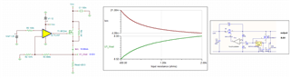
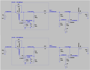
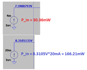
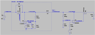
The source is a constant current 4~20mA from the left (Q3_p2), while the voltage on the right (Q3_p3) is fixed - when Isrc is 4mA, V_Q3_p3 is ~7.4V, when Isrc is 20mA, V_Q3_p3 is ~8.0V.

With Isrc within 4~20mA, output of U1 is always high (close to rail) as V- is less than V+, but we are observing that the consumption of the circuit is higher (40~70uA) when Isrc is lower (at 4mA), and consumption is lower by 30uA when Isrc is higher (at 20mA). On some boards, we are seeing >100uA, and just by swapping U1, we are able to reduce the consumption by 50uA.

Questions

1) What can the reason behind lower consumption (25uA less at higher Vdd)? Graphs provided in datasheet is showing otherwise.

2) We hope to reduce the number of reworks in production to fix the extra 50uA consumption of some op-amp, the results showing current consumption spread of 40~70uA, with a lot more exceeding 80uA. The data spread does suggest part to part variations, but we hope to confirm it.

Thanks,

SoonYet

  • Hi SoonYet, 

    1) What can the reason behind lower consumption (25uA less at higher Vdd)? Graphs provided in datasheet is showing otherwise.

    I converted the mentioned circuit into a simulation. If I understand correctly, you want to be able to control the Isrc or output current more precisely. 

    The circuit's transfer function is Isrc = U1_Vout/Rload. For instance, Isrc = 8.53V/426.5 = 20mA. U1_Vot is determined by Vref of 1.25Vdc. The REF3012 has 1.25Vdc +/-Errors. Rload may vary from unit to unit and TLV27L1 is not a precision op amp. All these variables that can create the current variation in this circuit, where U1_Vout = (866k/147k+1)(1.25V ± Vos). 

    OPA271 V-I Converter.TSC

    2) We hope to reduce the number of reworks in production to fix the extra 50uA consumption of some op-amp, the results showing current consumption spread of 40~70uA, with a lot more exceeding 80uA. The data spread does suggest part to part variations, but we hope to confirm it.

    In the simulation above, I plotted out Isrc vs. Rload. I assume that this is DC current application, If the Rload is more consistent, then the issues are likely TLV271 op amp and variations in feedback resistors. 

    If you are using 1% or better feedback resistors at 866k and 147k, you may try our low cost precision TLV07 op amp and it should improve precision of the circuit.

    TLV07 V-I Converter.TSC

    If you have other questions, please let me know. 

    Best,

    Raymond

  • Hi Raymand,

    Thanks for your reply.

    Allow me to explain more clearly, the circuit takes in 4-20mA current, and the output voltage is fixed by downstream circuit (R30,R31 divider and U4 Vref), also the downstream circuit will use and sink all the unused current into M2,R29. Due to series resistance R33 between the circuit and the downstream circuit, the op-amp V_U1 will be 7.4~8.0V depending on the supplied current Isrc, where Iout = Isrc - Icircuit, and V_U1= 7.41V + Iout * 33

    It has been tested with R3 bypassed, and the Vin+ reference supplied by precision benchtop power supply (meaning REF3012 circuit can be ignored), that the circuit consume 10uA more at low input Isrc=4mA compared to Isrc=20mA. Refer data in table below. This is part 1 of the mystery we are trying to understand, if the reduction is caused by op-amp design, as Iq/consumption usually increase with higher supply voltage.

    Isrc Vdd (Op-amp Vsupply+) Iout I_consumption (Isrc - Iout)
    4 mA 7.4 V 3.964 mA 0.036 mA
    20 mA 8.0 V 19.977 mA 0.023 mA

    For completeness, besides these operating conditions where the Vout always swing to max (comparator operation), there is another operating point where V_U1 is high enough that Vin- approaches 1.25V and op-amp starts regulating Vout.

    Do you think the comparator operation can cause unwanted/undefined behaviors described on this page? - https://www.analog.com/en/resources/technical-articles/maximum-supply-current-that-wasnt.html.

    Part 2 of the question is, that the higher consumption at 4mA input Isrc varies from part to part, and registered 35~80uA when tested at Isrc=4mA, and lower and smaller range (10~40uA) at Isrc=20mA. We confirmed by swapping op-amps between two boards that the current consumption follows the op-amp .The guess now for the different consumption of different parts is part variations but it is too much different that datasheet's max 11uA Iq value.

    Unfortunately we cannot use TLV07 due to lower power requirement, appreciate the suggestion.

    Regards,

    SoonYet

  • Hi SoonYet, 

    This is part 1 of the mystery we are trying to understand, if the reduction is caused by op-amp design, as Iq/consumption usually increase with higher supply voltage.

    I think that you may have to look at different way. The input power for two current sources are different. I will take a look at the Isrc current source, where the V-I efficiency to generate 4mA vs. 20mA is different. You may have to look at the problem from power efficiency point of view, where Isrc may be operating at different operating point, where generating 20mA is more efficient than generating 4mA in your current source. 

    You have to compare the two current sources with the same load, otherwise, it is difficult to figure out the issues. 

    Part 2 of the question is, that the higher consumption at 4mA input Isrc varies from part to part, and registered 35~80uA when tested at Isrc=4mA, and lower and smaller range (10~40uA) at Isrc=20mA.

    The circuit is basically driven from your current source 4mA and 20mA after Isrc. So this is I to V converter and driving 10ohm load. All the load power comes from Isrc at the current source based on the schematic. 

    The pmos in the following circuit if near off, and majority of voltage drop will be across M2's source and drain. Do you know what is load power at 10ohm between 4mA vs. 20mA conditions?  Power_in = Power_out, so all the power dissipation at the right has to be equal to power_in which is calculated in the first diagram. 

    If you have other questions, please let me know. 

    Best,

    Raymond