This thread has been locked.

If you have a related question, please click the "Ask a related question" button in the top right corner. The newly created question will be automatically linked to this question.

THS4082: Stability of peak detector circuit contains two stage amplifier

Part Number: THS4082
Other Parts Discussed in Thread: OPA171

Tool/software:

Hi Team, 

              i am working on a problem , and i need your help to identify the approach. 

1) info;- we are working on peak detector circuit as shown below, so here we are trying to find out the stability of the 1st Amplifier THS4082(U3),where the signal is injected. 

2)info;-  i have gone through the stability theory from TI precision lab, but most of them are for single stage amplifier, simple feedback loop and  non inverting amplifier, in my case this is little complex as it involves two amplifier and feedback taken after 2nd buffer.

3) Query;- As per indirect method of finding stability, i wanted to understand for which point of circuit i should check the % overshoot OR gain peaking ??

4) Query:- if i used direct method where i should break the loop ,and what about 2nd amplifier buffer loop and  for this type of circuit how we can get Aol*B curves??

5) info;- we are using LTspice for stability analysis.

  • Hi,

    Stability analysis for composite type circuits gets way more challenging than the method in TI Precision Labs like you mentioned. I went ahead and attached a TINA simulation showing where you can break the loop to capture loop gain (Aol*B). You can break the loop in a few places, but ideally should all result in the same value. You could try the indirect method and measure at the outputs of the amplifiers but breaking the loop and finding the loop gain is your best bet for finding the stability of a circuit. I was able to simulate the circuit and found that it had no phase margin. This is due to the heavy capacitor load at the output of the first amplifier. After adjusting numerous components, the best way to get it stable was through adding a feedback capacitor across the THS4082 in parallel with the diode. This creates local feedback at high frequencies and helps stabilize the first amplifier. It will slow down the circuit but depending on the input signal frequency, it could be enough for what you need. You could adjust the charge capacitor, which should allow you to reduce the feedback capacitor, but it is at the expense of faster discharging.

    Best Regards,

    Ignacio

    PeakDetector_THS4082.TSC

  • Hi Ignacio, Thanks for your reply, i gone through your simulation file, and i have many doubt, i will ask one by one;-

    1) As i see in your file , you have break the loop at the out put of the 1st op-amp, that i didn't understand why, As per some TI video i have seen for multi feedback loops, we can break the op-amp inverting input side that breaks both the loop, but in your case the resistive feedback loop from 2nd amplifier is still connected, please explain the reason .please check my understanding from below video.stability-6-isolation resistor.

    Precision labs series: Op amps | TI.com

     2) i tried the 2 indirect method % overshoot and gain peaking. but before that my concern for both method, for my circuit either i should monitor output  at the 2nd Amplifier output pin, OR 1st amplifier output pin. should i check gain peak at the out put of 1st amplifier only always?

    3) As i have tried the indirect gain peaking method also  , but for 200pf i see the gain peaking is still there, that reduced and becomes flat on 50nF, but that i see very high value, please suggest , 

    4)  As per % overshoot method we need to apply a signal that generates on output a step size of 10mV approx., that is not happening with this circuit when i am applying input to inverting input. 

    5) and last i think we both have different models so i am sharing my circuit.

    peak detector with my model.TSC

    6) can we compensate this stability through a cap. parallel to feedback res. from amplifier 2??

  • Hi,

    I was able to simulate the circuit breaking the loop at the input and attached the simulation. With the feedback capacitor across the THS4082, the device showed good phase margin. For the indirect methods probing at each output should give some indication whether a circuit is unstable. The concern here is that the bias point of the circuit might not be defined when running an AC sweep due to the diodes not being on, which would cause erroneous simulation results. You could run a transient simulation and measure both outputs to see if there is any ringing or oscillations. The transient sim should allow the device to be biased appropriately since only one diode will be on a time and should be capturing what the circuit is doing more accurately than an AC sweep.

    If you are using the transient simulation to find potential instability signs, I believe a 10mV will not do anything to the circuit as neither diode will be forward biased to turn on. The method highlighted in the precision lab videos are for ideal standard circuit configurations which would likely not work as highlighted in this scenario. However, you could still run transient simulations to see if the output signal rings. This is a quick sign that the circuit is unstable.

    As for compensating by adding a feedback capacitor in parallel with the outer resistor, I do not believe this will have much effect as the main delay is coming from the path through the OPA171. At high frequencies we want to create a faster return path for the THS4082 which is done with the feedback capacitor. By adding a feedback capacitor across the outer resistor, the delay is still present through that main path. I was able to simulate this configuration, and it did not really improve the phase margin when doing so. 

    Best regards,

    Ignacio

    PeakDetector_THS4082Stability.TSC

  • Hi Ignacio, thanks for your reply and effort, this solution is very much as per my understanding, but i am confused at one point for 350pf also my circuit is stable as per phase margin value 58' and it's also showing stable for 10pf 67.57', but for my actual signal 400khz and 12.5v peak, circuit output from 2nd amplifier has some disturbance and oscillation for 10pf, for 350 its working fine.. please guide why its showing stable on 10pf. also note i have removed L2 -1T and shorted and i see it was not having any impact in final results of ac analysis.

  • Hi,

    I wanted to quickly check something in your simulation. For the 10pF case, if you reduce the signal frequency to say 1k does the output behave as expected?

    Best Regards,

    Ignacio

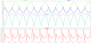
  • HI Ignacio, sorry for late reply, for 1khz also 10pf cap. across diode not improving stability, i have attached both the results for 350pf and 10pf, you can see how good is 350pf one, but our method shows stability for 10pf also. 

    Please note that circuit shared here is only half part, before that there is one precision full rectifier circuit. 

    response for 10pf: - 


    response for 350pf 

  • Hi,

    The only thing I can think of is the added effects of the diodes when running a transient simulation. In the stability analysis we have to assume one diode is open and one is biased which ideally is a short. However, I am not certain how the diode is modeled, which could be the reason the transient simulation shows nonideal results that the stability simulation is not accounting for. I would trust the simulation with the increase of the feedback capacitor as this would make more sense in getting the circuit stable.

    Best Regards,

    Ignacio