Other Parts Discussed in Thread: OPA391, TINA-TI
Tool/software:
Dear Team,
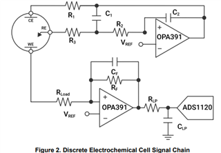
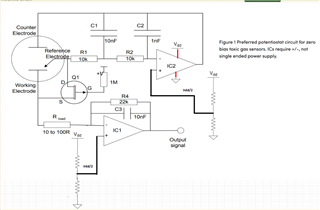
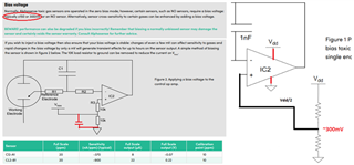
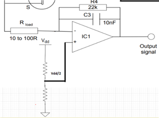
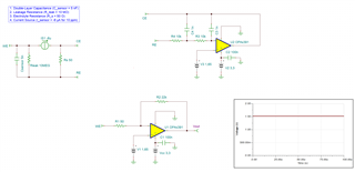
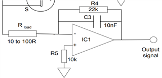
I will be using OPA703 for implementing the circuit given below.The circuit is obtained from here.
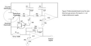
I did not completely understand the above circuit.My questions are given below.
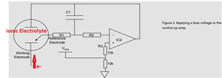
May I know how this circuit maintains the Potential at Reference Electrode and Working Electrode same.
Here you can see that the working electrode is connected to IC1 and Refrence electrode to IC2.They are not in a common loop.Then how this circuit maintains same potential at working electrode and reference electrode.
Regards
HARI