This thread has been locked.

If you have a related question, please click the "Ask a related question" button in the top right corner. The newly created question will be automatically linked to this question.

OPA210: TI-Pspice simulation Converge issue

Part Number: OPA210


Tool/software:

Dear TI-PSPICE team

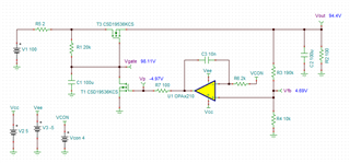
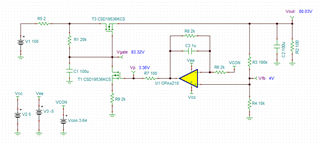
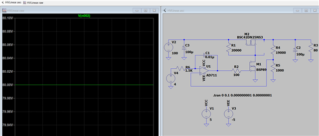
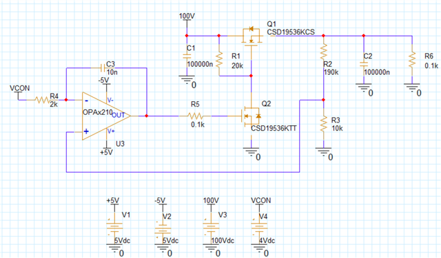
I use TI-PSPICE to simulate a high voltage discrete linear regulator for my customer. however, I meet converge issue even I update simulation conditions. could you please help to solve converge issue? my schematic as below figure shows. also attached my schematic file in here for debug the issue. thanks a ton!

LDO.DSN

regards,

Bill

  • Hi Bill, 

    What Vout are you trying to regulate at the output? What is the output current requirements? Is it up to 1Adc? 

    For the NMOS series regulator, the gate voltage at Q1 has to be greater than Vout in order to turn on the Q1. My guess is that you may consider to use PMOS at Q1 for the design configuration. 

    Please provide the above information and I will figure out why issues are. 

    Best,

    Raymond

  • Hi, Raymond

    thanks for supporting. the VCON=4V, adopt voltage has a coefficient of 20, so the expected output voltage is 80V. the output current need big than 2ADC and big than 10A transient.

    yes, PMOS is easy drive in here. but TI has no PMOS can endure voltage big than 100V. also, NMOS has more choice than PMOS in market, so, I prefer use NMOS in here. the R1 in here provide a potential dive channel to Q1. it is said, that R1 & Q2 build a voltage divider and drive Q1.

    let me know if your have further problems. thanks.

    regards,

    Bill

  • Hi Bill,

    The circuit has issues. When the 100Vdc is powered on, Q1 is turned on and the output will be approx. 94Vdc.

    The error amplifier is connected at non-inverting node and Q2 will never be turned on due to the negative gate voltage at ~ -5V. 

    80Vdc Series Regulator Not Working 05092025.TSC

    You need to find a way to control the gate voltage at Q2. Typically for this type of series regulator, it is using a negative feedback. So we do not have the integrator here, and it needs have an error amplifier (integrator for the design). The convergence is likely to do with the OPA210's configuration, and you do not need to use the high end op amp for this circuit. A general  purpose or regular precision op amps will do fine as the error amplifier. 

    The reference voltage is the most important part of the series regulator. It it is noisy, the output will  be noisy. 

    If you have other questions, please let me know. 

    Best,

    Raymond

  • Hi, Raymond

    the circuit seems has no issue. let us to do a draft analysis. 

    1. if the output is higher than expected, then the non-inverting input of error amplifier will higher than expected and output of error amplifier will vary higher. this will cause D pole of Q2  down. and then output voltage will low.

    2. if the output is lower than expected, then the non-inverting input of error amplifier will lower than expected and output of error amplifier will vary lower. this will cause D pole of Q2  rise. and then output voltage will higher.

    so, it is a negative feedback system.

    here is simulation result that I use other software.

    https://e2e.ti.com/cfs-file/__key/communityserver-discussions-components-files/14/HVLinear.asc

    also, attached simulation file for reference. 

    let me know your comments. thanks.

    regards,

    Bill

  • Hi Bill, 

    You only analyze two scenarios when the output is different from the setpoint. What happened when V_error = 0, this is where an integrator is really needed. If the circuit requires to have accurate regulation, you need to have a true integrator for the Error Amplifier for the feedback loop. Try to inject a pulse load at output, and see how the regulator behaves. I think that will oscillate.  

    I can not use LTSpice simulation over E2E. You have an integrator, however, you are feeding the V_feedback node to non-inverting node. Typically, it is opposite. The circuit may potentially have stability risk. I recalled that Vref (e.g. 4.00V) should be connected to non-inverting input, and noise on that node is gained up at the regulator's output, not attenuated (I think that this is what you have). You have to do loop analysis in order to figure this one out. 

    If you have other questions, please let me know. 

    Best,

    Raymond

  • Hi Bill, 

    I forgot to mention that LTSpice is using much relaxed convergence criteria by default, such as RELTOL, VNTOL, ABSTOL than PSpice or Tina simulating environment. Tina is better than PSpice in that respect. You can change these default setting, but I prefer to use Tina simulator. For simulating DC regulators and switching regulators, LTSpice has some advantage (better nonlinear simulating model, forgiving integration models and optimization). But please keep in mind that it does not mean that the circuit will work, when you put it together on a board (you still have to fine tuning many of these power circuits).   

    Best,

    Raymond