This thread has been locked.

If you have a related question, please click the "Ask a related question" button in the top right corner. The newly created question will be automatically linked to this question.

PGA308EVM: Input siganl and offset calculation

Part Number: PGA308EVM
Other Parts Discussed in Thread: PGA308,

Tool/software:

Hi team,

we want to test the output behaviour of the PGA308 EVM and therefore we want to attach a differencial 1mV sinusoidal signal to the inputs with 500Hz and a common mode voltage of 1.65V.

is it possible to connect directly a sinusoidal signal from a signal generator at the input pins of the PGA308 EVM without the sensor? I am asking because the signal are referenced to ground and also from where can I take the common mode voltage?

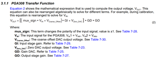
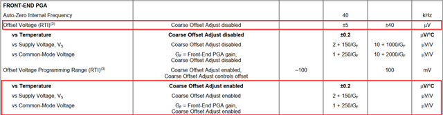
My next question is related to the Offset calculations. If I don't use the Coarse Offset Adjust I don't need to take into account all Coarse Offset Adjust enabled values, is that correct?

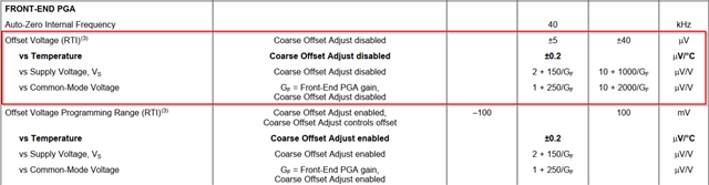
The other way around I need to consider all Coarse Offset Adjust enabled values if I enable the Coarse Offset Adjust. In this situation which value can I take for the genral offset voltage? The offset voltage mentioned in the datasheet is for the Coarse Offset Adjust disabled.

I am looking forward to your answer.

Best regards

Felix

  • Hello Felix, 

    This can be done; however, I recommend a better way to evaluate the PGA308 is to use the built-in sensor emulator of the PGA308EVM. 

    If you would like to proceed forward with the signal generator, here are a couple things to consider. 
    Here is the transfer function for the PGA308: 

    Assuming power supply and reference voltage is 5V. 
    The following settings would show an ideal output of 0.2V: 

    Ideal output: Differential Input (1mV) * Front End PGA (100) * Output Amp Gain (2) = 200mV 

    Offset voltage is referred to input = (Actual output - ideal output)/(Gain)

    Let's say instead the output measured 205mV, offset voltage RTI = (205mV -200mV)/ 200 = 25uV

    Notice how "gain" is front end gain and output gain as it is a signal chain. Is this enough for evaluation? 

    All the best,
    Carolina

  • Hi Carolina,

    it is great to hear from you again!

    Do I understand it correctly that the sensor emulator is the simulation part in the GUI? Are the steps necessary for setting up the simulation?

    The EVM is intended to use to make a EMC test with it. Therefore the signal generator will be taken to provide the input signal. Can you please help me to understand how the signal generator can be connected to the EVM pins? 

    What would you suggest? My idea is to use the signal connection for Vin1. For Vin2 would be then the ground connection of the signal generator? 

    Thank you also for the calculations in the simulation. Can I take the calculation from the simulation for the ideal offset calculations? Can I calculate in there also the temperatur offset?

    Best regards

    Felix

  • Hi Felix, 

    Good to hear from you again, thanks for the additional information on EMC test. Do you know what standard you are trying to pass? 

    In this case, I would not use the sensor emulator.

    I would use the USB-DAQ & EVM GUI to program the PGA308 and then continue to use it in standalone mode. Details on standalone mode can be found in Section 5.5 of the part's User's Guide: PGA308 User's Guide (Rev. B)

    I would connect one of the inputs to 1.65V and the other to a function generator driving a sine wave 1mV around 1.65V. The programmed values inside the PGA308 would match the simulation screen capture above. The offset would be calculated the same way. 

    For temperature offset drift, what is usually taken is the offset across the temperature range and a slope is fit to it. In this case it looks to be 0.2uV/C. Here is an example, I've attached my excel as well if you need more examples: support.xlsx

    All the best,
    Carolina