This thread has been locked.

If you have a related question, please click the "Ask a related question" button in the top right corner. The newly created question will be automatically linked to this question.

INA138: Current measurement

Part Number: INA138

Tool/software:

Dear All,

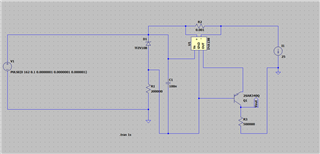
I want to use the below schematic to measure current in a 3 Phase inverter - i.e. to measure Phase voltage.

What is wrong in the below schematic. 

1. When I supply DC voltage it provide a correct o/p voltage 

BUT

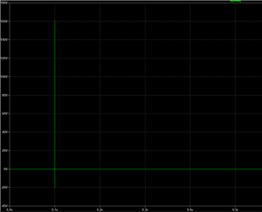
1. When I provide a 1 micro second pulse it provides a very high o/p voltage. 

How to fix the issue

OR may be I have to fix the issue on how we are sampling the current for measurement ?.

The inverter will be working with 20-25 Khz switching frequency ....

O/P waveform when i provide a 1 microsecond pulse input 

  • Harish, 

    Based on the schematic, I'd say this is likely a saturation issue. INA138 is a unidirectional amplifier, and as such it can only measure current in the forward direction. It cannot measure reverse current nor can it measure true zero, as you drive the amplifier into the ground rail when you attempt to do so. Once the output is saturated, the output will recover once it is returned to normal operating conditions, but this return can come with time and output irregularities such as this. You can test this theory by adding a small DC offset of current to the load to pick the device up off of GND and see if this corrects the output.