This thread has been locked.

If you have a related question, please click the "Ask a related question" button in the top right corner. The newly created question will be automatically linked to this question.

Bipolar constant current source for capactive loads

Other Parts Discussed in Thread: OPA404, INA114, XTR300

Dear all,

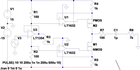
I'm trying to build a bipolar constant current source to drive capacitive loads and I really hope you guys can help me out!

My requirements:

- the load is a micro-electrode, which can be modelled by a grounded C-R circuit (R~7k and C ranging from 10n to 3uF in series). As said, the load is grounded and capactively dominated.

- Vin is a rectangular bipolar pulse (f~25-200Hz with a pulse width of ~200us), which should be converted into a bipolar current pulse with amplitudes from 1-10mA.

Not-so-well working ideas:

- Improved Howland current pumps (using OPA404). Worked quite nice but only for small loads (10n-1uF) and low amplitudes (up to max. 1.5mA). If I exceed these, the current pulse breaks down or gets smoothed (not rectangular any more).

-Differential voltage to current converter (as specified in INA114 datasheet - Fig.13; the second OPA was also a OPA404). Works great for resistive loads but not for capacitive ones.

- using the XTR300. Well, in principle is has the same archtitecture as the diff. VCC as described above with the same limitations.


So am I doing something terribly wrong and one of these ideas should work or is there a better way to build something like this up? Using a transistor current source maybe?

Thank you very much for your ideas and time!

Kind regards,


  Tim


  • Tim, the issue I believe you are having is due to the limited output voltage range of an opamp. Any time you try to drive 10mA though a resistance of 7kOhm, you're going to need 70V to do it. On top of that, many opamps do not like to drive capacitive loads which can introduce instability issues. If it is possible to float the electrodes you may have some luck using a modified version of the circuit shown in this thread (using an external BJT or FET):

    http://e2e.ti.com/support/amplifiers/etc_amplifiers__other_linear/f/18/t/150368.aspx#545484


  • I should also point out, from my own personal experience in graduate research, that micro-electrodes generally don't like to dissipate .7 Watts (P=I^2*R). You may be surprised that due to the small mass, and therefore inherently low thermal inertia, how rapidly these structures heat up.

  • Hi John,

    Thanks for your thoughts. Power dissipation should not pose a problem since the electrodes are imerged in saline solution. The idea here is to build a pulse tester. My electrodes are made out of platinum or iridium oxide (80um in diameter, hence the capacitance) and I want tol see when they hit the water window (induces corrosion). So I want to drive them near the water window (monitored with a reference electrode) and observe the maximal current they can withstand. Unfortunately, they have to be grounded to do that. 

    Compliance voltage is the limiting factor within the Howland approach, so your right there! A 70 V source is hard to come by within our labs, so is there another way to drive the electrodes anyway? May a transistor source be able to do it? It should not have the problem to drive a capactive load at least, or am I wrong there?

    I would be gracious for any idea!

    Cheers, Tim

  • Hi, I guess I found yet another circuit that may do the job (see graphic), but somehow I couldn't get it to work. I tried with the given components and the negative phase works fine but the positive phase is blocked....

    Could you give me a hint with which components of yours the circuit would work?


    The MOSFETs should be power MOSFETS and U1 & U2 rail-to-rail OPAs....R7 is used as sensing resistor to monitor the current and voltage drop over the load (C1 & R6).

    Thank you very much,

      Tim


  • Tim,

    To start, I think you should look at the power supply connections on U1. I also don't think this circuit will be able to provide 10mA to your load. No matter which circuit topology you chose, it still must obey Ohm's Law, which requires you to apply 70V across a 7kOhm load in order to get 10mA through it. Without a 70V supply, one possible route would be to search for a wideband transformer that would allow  you to step-up the output voltage across the load, however this will definitely affect your pulse shape.