A related question is a question created from another question. When the related question is created, it will be automatically linked to the original question.
If you have a related question, please click the "Ask a related question" button in the top right corner. The newly created question will be automatically linked to this question.
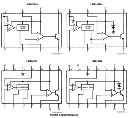
Is it correct that the EMIT terminal does not output an output voltage higher than the power supply voltage? For example, if the input voltage of 6pin (V+) is 4.5V and the input voltage of 1pin (TACH+) is MAX 5V, the MAX output of EMIT is recognized as 4.5V.
That is correct. EMIT is the emitter of the bipolar junction transistor. It won't be able to output anything above the supply rail. And as you mentioned, it won't be able to output up to the supply rail. It will have some voltage drop across the collector and emitter.
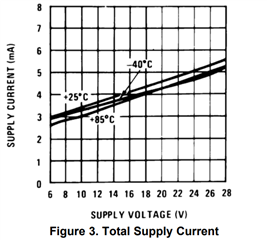
I never noticed that the datasheet doesn't specifically state this. It does state it indirectly when looking at the Electrical Characteristic graphs. As shown below, the graphs will only show going to 6V not lower. The device hasn't been characterized to go below 6V.
Robert is out of office, I will continue the support in the meantime.
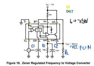
1. The Vcc in the formula is 7.56V
This can be confirmed by Vo = VCC * f * C1 *R1 = 1V/66Hz = (7.56V) * f * (0.02e-6 1/ohmHz) * (100e3 ohm)
2. There is a way in 14 pin version but not in the 8 pin version. The 14 pin version, pin 11 (TACH-) is separate from ground. The 8 pin version cannot do this:
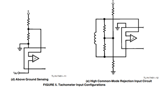
Here are two examples of how to do this for 14 pin version:
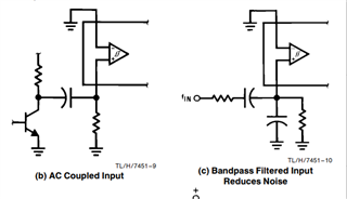
If you choose to use the 8 pin version, can always AC couple the input:
3. The input terminal does not need to exceed the Zener voltage.