This thread has been locked.

If you have a related question, please click the "Ask a related question" button in the top right corner. The newly created question will be automatically linked to this question.

OPA817: PTMUXS7614DZEMR

Part Number: OPA817

Tool/software:

Hello,
I would like to ask for help regarding the usage of the PTMUXS7614DZEMR in a switchable gain op-amp circuit.
Attached is the circuit in question. For some reason, the output of the U9 op-amp oscillates at 4 MHz. I’ve tried modeling this circuit in several simulation programs (including the one TI uses), and the simulations always show correct behavior.

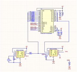
However, I do not have a model for the MUX switch.
Could someone please take a look at the circuit and help identify why it is behaving erratically? I can’t seem to pinpoint the issue.
The signal from U36 op-amp is very clean and stable, so the OPA817 appears to be working properly. I also have two identical channels, and both behave the same way.
The MUX appears to be working and correctly switching the resistors. In this scenario, my signal goes up to 10 MHz, which should be well within the PTMUX’s 180 MHz bandwidth.
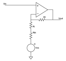
Ok, Missed that feedback virtual offset point has tones of capacitance (I was only thinking about output capacitance ), meaning each resistor needs to have correct capacitor soldered on top
  • Hi,

    I believe the issue you are seeing is due to the mux in the feedback path of the OPA817. As with any high-speed amplifiers, any parasitic capacitance along the feedback network can have major effects on the stability of the circuit. It is the mux which has internal capacitance that is delaying your signal and is likely the reason you see an oscillation. In general, we do not recommend this type of circuit because of this delay. Could you try maybe placing a feedback capacitor in parallel with the whole mux circuit to see if this helps stabilize the circuit. I would start with something like a 1nF and adjust up or down as an option to see if you can stabilize the circuit.

    Best Regards,

    Ignacio

  • What’s strange is that I desoldered the MUX, placed a direct short across the 1kΩ resistor MUX path, and even lowered the R37 resistor to 250Ω — yet the issue remains exactly the same... At this point, I’m completely lost.

    For reference, I have four other OPA817s in non-inverting configurations (such as a DAC offset buffer), and they all work without any issues.

    I also added a capacitor (Cf) across the feedback resistor, but it had no effect. This is getting more and more puzzling. (Cf based on capacitance should be 68pF with MUX present)


  • Hi Linas,

    Thats good you removed the mux and have just a feedback resistor, this will give us a good baseline. Could you remove the capacitor connected to IN+ (C60). Due to the input structure of a device, sometimes having a capacitor directly to the non-inverting input kicks up an oscillation. Could you also share the decoupling capacitor configuration for this particular OPA817. We have seen oscillations due to lack of proper decoupling on the supply pins. 

    Best Regards,

    Ignacio

  • Hello,

    I spent some time reconfiguring to the non-inverting option. It behaves better, but a 4.2 MHz oscillation still remains. While it is barely visible with large inputs, it is noticeable with small inputs.

    In this configuration, the capacitor is no longer connected to any net, yet the oscillation persists.

    Regarding decoupling, there are multiple capacitors and a solid ground plane, so I believe it’s adequate in this case.

  • Hi Linas,

    Thank you for trying this debug step. I was wondering if your layout had plane cutouts under the inverting node and output node as well. This is a fairly fast device and having planes under these pins could result in stability issues. Could you also share what the output is going to? For debug purposes it might be good to disconnect any load as well if you have not done so already. One option, if possible, could be to swap a different OPA817 and see if you see an oscillation. Partially damaged devices can still function but show erroneous results.

    Best Regards,

    Ignacio