This thread has been locked.

If you have a related question, please click the "Ask a related question" button in the top right corner. The newly created question will be automatically linked to this question.

INA849: Distortion at 10KHz and 100KHz

Part Number: INA849

Tool/software:

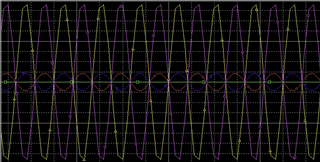
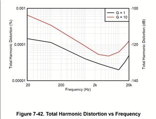
I am considering the INA849 for an instrument design. The data sheet shows good distortion at 1KHz. The spice model shows unrealistically low distortion in simulation

What is the distortion at 10KHz and 100KHz, at moderate output swings?  I will power the OPA849 with +/-15V, and require an output swing of no more than +/-4V into either 10Kohms or 100Kohms. The gains of interest are 40dB (100V/V) to 60dB (1,000V/V). The actual circuit will provide gains from 0dB to 60dB in 10dB steps. If necessary to keep distortion very low, I can limit the output swing to +/-1V.  In order to provide a small degree of input protection, the inputs will have series resistors of 200 ohms.

Hopefully TI has characterization data for this application.

Thank you,

Morty Tarr

MTarr Consulting LLC

  • Hey Morty,

    Depending on what SPICE engine you are using, it is probably due to the SPICE engine doing a piecewise linear approximation of the input source and measured output. Therefore if the steps of the piecewise function are not small enough to capture the distortion due to the amplifier, both the input source and output signal will have the exact same "distortion" resulting in an unrealistically low distortion value.

    Here's a graphic example. Below I measured a 60Hz signal for 1 second, and the output directly from the source looks like the following. This is because the maximum time step is defined in PSpice by the simulation time. Essentially you start running into the nyquist limit. This can be overcome by setting a smaller maximum step size.

    Back to your original question though, we do not have characterization data for distortion at +/-4V at 100kHz in a gain of 100V/V or 1000V/V into a 10k or 100k load.

    However, looking into the slew rate needed for a 8Vpp sine wave at 100kHz, (pi*f*Vpp) you need 2.5V/usec of slew rate (INA849 slew rate is 35V/us, we want to be far far away from this number). The best we can provide is either bench measured data from a single unit, or an estimate based on the provided data in the datasheet.

    For G10 we can see that we are below 100dB of THD, for gains of 100 and 1000, we will likely be at less than 70-80dB of THD.

    Best,
    Gerasimos

  • Hi Gerasimos,

    I am using LT Spice v17.1.11. I set the simulation to use 256K (262,144 points) over 9 cycles so I can use a rectangular window for best resolution. I set LT Spice to double precision math. I can detect distortion below -150dB with this configuration. All this is done with parameters, so it is exact.

    I would like to use the INA849 as part of a front end for test equipment. It has to have vanishingly low distortion (better than -100dB, preferably -120dB). I am trying to confirm this with spice so I can be more confident moving to PCB design. Since the INA849 model is a macro model, it is hard to be certain that it accounts for the distortions I am concerned about. I understand that the spice representation will not exactly replicate what I see in "real life", but it is an indication of the right path or the wrong path.

    Perhaps TI could send me an INA849 eval board?

    Thank you,

    Morty Tarr

    MTarr Consulting LLC

    PS: I use this older version of LT Spice so my simulations correlate to each other. Also, I understand the correlation of these simulation to bench performance. The changes to the underlying math are not usually disclosed for updates, which is understandable.

  • Hey Morty,

    I do believe that silicon will probably be your best bet for accurate measurement of THD. The macromodels detail what parameters are characterized in the header. The output of the amplifier is modeled with an idealized output source (VCCS) that will not give you any distortion in the cross-over region, and the AOL is static over loading conditions and output voltage range. The swing from rail over Iout is also modeled with an internal sense node and clamping structure. All of this to say that many of the factors that contribute to distortion are not going to be behave accurately in the model.

    Additionally, since there is not a method to break the internal loops of the instrumentation amplifier in silicon, the internal amplifiers are modeled based on the analog design simulations, which are good, but in my experience tend to be optimistic. Generally unless you are running into gross violations of swing or any large signal operational limits of the device like slew rate, the distortion will likely be overly optimistic in SPICE and solely be a function of the devices typical Aol. Below is the header for the INA849 Model to show which parameters are characterized in the model.

    As far as getting an EVM, do you have a TI Field Applications Engineer point of contact? Otherwise, I'm unfortunately unable to send you an EVM.

    Best,
    Gerasimos

  • Hey Morty,

    Did this answer your questions?

    If so, please let me know. If you have further questions, feel free to respond.

    Best,
    Gerasimos

  • Hi Gerasimos

    I agree with the assessment that the model results are optimistic. Time to look at the silicon to see what it does. 

    My salesperson at TI has recently been reassigned. I'll have to find out who to contact about this,

    Thank you,

    Morty