Tool/software:
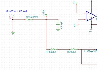
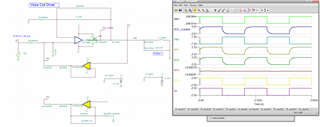
I am designing a voice coil driver to drive a Fast Steering Mirror. I have found some similar designs on this forum, and basing my design on these. The coil resistance is 8 ohms, and I estimate the inductance ~200uH. I need to generate 1A drive for 10V in. It is a bi-polar drive. One goal is to minimize the sense resistor beacuse of power dissapation. I can use a 1-2W resistor here. So a 1 ohm or less is preferred. Questions I have..
1. Should I achieve the required gain with U1, or by the sense resistor or by the R3/R2 ratio. Currently using R3/R2 ratio.
2. Does one of these make stability easier. I have not analysed stability in transconductance amplifiers before, but followed a similar post on the forum to do this.
3. The snubber circuit seems to be important in the stability analsyis. I can change these value once metal is cut, but what value should I use for this simulation?
4. I have not used bypass caps in simuilation tools before. Are they really required?
5. I can procure 0.01% resistors for matching. Is this precision required, Is 0.1% good enough?
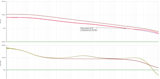
Below is ac analysis to examine stability. I notice noise at low freq in the phase. THere is also a bump in the phase around 4khz. Would appreciate comments and improvement in the circuit.