This thread has been locked.

If you have a related question, please click the "Ask a related question" button in the top right corner. The newly created question will be automatically linked to this question.

INA236: INA236 BGA

Part Number: INA236

Tool/software:

Hello

We are using the INA236 BGA to measure the current drawn by a +5.0V Device within our system

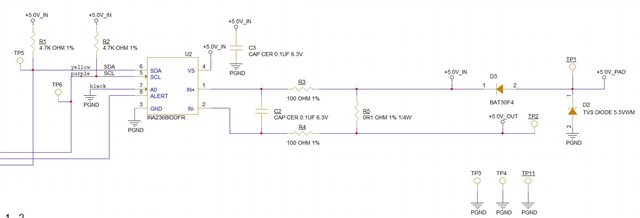
+5.0V IN    is used for the INA236 and microprocessor power

the +5.0V Device is connected to TP2 and TP11 - Therefore we are using high side sensing

We are using the BGA Version of the INA236 

The yields we are achieving in production are very low on the first run (approx 34%)

We measure short circuits which do not show up on the XRAY of the PCB but if we remove the INA236 BGA Device the shorts disappear

We are going to design out the BGA version and use the SOT23-8 version to help with yields (hopefully)

  1. Can you spot anything wrong with the schematic ?
  2. Are R3 and R4 required ?

Thank You


KR

Paul H

  • Hey Paul,

    Here are my responses to your questions:

    1. The schematic does look good to me. The only thing I can think of is that I notice the ground is called "PGND", from this I presume that there are other grounds in the system. You will need to make sure that the INA, Load, and MCU all share the same ground, otherwise you may be damaging the device. (unless you use isolation). If they all already have the same ground, then my next guess would be a manufacturing issue (which would be tested when you switch to the SOT23 version).

    2. No, R3 and R4 are for optional input filtering. If you don't need to filter the input, then you don't need the resistors. 

    Regards,

    Mitch

  • Hi Mitch

    Thank you for your prompt answer

    We have since found out that the device could be getting damaged by ESD and have added a 30KV TVS 

    but the design team wish the following question answered

    The datasheet talk about 10ohms resistors - Are these the same resistors as the 100ohm resistors in Fig8-1

    We have added a 30KV TVS between the Load Supply/GND across the Load

    Comments Please

    Thank You

    Paul Humphreys

  • Hello Paul,

    Yes, the 10Ω resistors mentioned in the text is for the same location as the Rfilter resistor that has a limit of <100Ω in the diagram. 

    Regards,

    Mitch