This thread has been locked.

If you have a related question, please click the "Ask a related question" button in the top right corner. The newly created question will be automatically linked to this question.

INA181: Whether customer can change the total gain of the sensing circuit based on INA181 by change the external RF resistor value

Part Number: INA181

Tool/software:

Hi Team

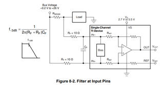
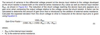
As I describe on the title, customer needs their current sensing circuit gain as: 100V/V>Gain> 75V/V, so they wanna change the Rf resistor to get their requirement.

They changed the Rf resistor to change the circuit gain, when they set Rf as165Ω to get gain as 85.8.

they tested the gain and found it was 85.8 indeed. 

So whether customer can change the circuit by this way?  are there any potential risk for this use-case? 


  • Hi,

    Here are a few things to pay attention to:

    The system gain will spread. In other words, over a large population, the distribution will widen. By itself, the INA181 has a very tight gain distribution.

    The properties of Rf resistors and internal resistors are different, so drift will get worse.

    Unless the Rf resistors are exactly equal, they will contribute to offset.

    Regards

    Guang

  • Thanks Guang

    1. Why the properties of Rf and internal resistor are different?  Internal resistor is equivalent to semiconductors? or it is just that the spec of internal resistor are better?

  • Hi Harry,

    The internal and external resistors are manufactured on different processes, by different manufacturers. Material property will most likely be different.

    The specs of the internal resistor may not necessarily be better.

    Regards

    Guang