This thread has been locked.

If you have a related question, please click the "Ask a related question" button in the top right corner. The newly created question will be automatically linked to this question.

INA818:accuracy

Part Number: INA818

Tool/software:

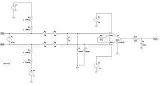
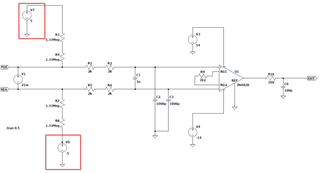
INA818を使用していますが、電源電圧が±14V、ゲインが128の回路に温度を加えると、データシートに規定されている以上に精度が劣化します。そこで-14Vを-10Vに変更したところ、精度が向上しました。中点がシフトされていない場合、データシートに規定されているよりも精度が低下する理由は何でしょうか?

  • I am using an INA818 and when I apply temperature to a circuit with ±14V supply voltage, gain 128, and Vref=0V, the accuracy degrades more than specified in the datasheet.
    So I changed the -14V supply to -10V and the accuracy improved.
    If the midpoint is not shifted, why would the accuracy be less than specified in the datasheet?

  • Hi Tanaka-san, 

    Could you help to answer some follow up questions about your application so I can better understand the issue? 

    • What temperature range are you applying to the circuit? 
    • Do you have a schematic of the input and output connections to the INA? 
    • How much is the accuracy degrading? And how are you measuring this? 
    • What are the input conditions when you are testing this circuit? 

    Thank you!
    Regards.
    Ashley

  • I will answer below.

    ・What temperature range are you applying to the circuit?

        ⇒  From 25℃ to100℃

    ・Do you have a schematic of the input and output connections to the INA?

    How much is the accuracy degrading? And how are you measuring this?

      ⇒ accuracy:-0.33mV~+0.53mV

        accuracy:-0.018mV~+0.001mV(V4:-14V ⇒ -9.6V)

    ・What are the input conditions when you are testing this circuit?

      ⇒21mV 

    Regards.

    Tanaka

  • Hi Tanaka-san, 

    Thank you for the additional information. 

    Are these +5 and -5V sources also applied on the input side? What is the output voltage measurement? 

    Also are you checking at temperature extremes for accuracy or looking at drift across temperature? 

    Regards,
    Ashley

  • I will answer below.

    ・What temperature range are you applying to the circuit?

        ⇒  From 25℃ to100℃

    ・Do you have a schematic of the input and output connections to the INA?

    How much is the accuracy degrading? And how are you measuring this?

      ⇒ accuracy:-0.33mV~+0.53mV

        accuracy:-0.018mV~+0.001mV(V4:-14V ⇒ -9.6V)

    ・What are the input conditions when you are testing this circuit?

      ⇒21mV 

    Regards.

    Tanaka

  • ・Are these +5 and -5V sources also applied on the input side? What is the output voltage measurement? 

      ⇒Don't worry about this as it is the excitation voltage for the external sensor.

    ・Also are you checking at temperature extremes for accuracy or looking at drift across temperature? 
      
      ⇒We are investigating drift due to temperature.

    I would like to report the results of my research on op-amps.

    ・With a ±14V power supply, the reference point is 0V, so if the input is 5mV or 21mV, it will overlap with the crossover region, which will increase the effects of temperature drift in the internal transistors and reduce accuracy.

    ・As a solution, if the reference point is raised so that the input range does not overlap with the crossover region, it will no longer be affected by temperature drift and accuracy will improve. As a result of testing when the -14V power supply was changed to -9.6V, the reference point became 2.2V, which no longer overlaps with the crossover region and therefore accuracy was improved.

    ・Is it correct to think of the reference point as being the maximum voltage of the input range + approximately 1V?

  • Hi Tanaka-san, 

    What type of sensor are you interfacing on the input? Are you using this when you are measuring the system? The reason to understand your sensor input is that this will set your input common mode voltage. And when the supply voltage changes, this impacts the swing range internally in the device. 

    The reference voltage relationship with the other parameters is more complex for an instrumentation amplifier as you can think of it as 3 operational amplifiers inside of one device. You set the reference voltage externally with the Vref pin and in your application, you are setting it to 0V. Changing V+ or V- impacts the swing range internally in the op amps and can then impact the linear operating range. 

    For more information on INA structure, please see this TI Precision labs video.

    Please help to clarify the input and output conditions and measurement results as it can help us better troubleshoot the issue and find a solution. 

    Thank you!
    Regards,
    Ashley