This thread has been locked.

If you have a related question, please click the "Ask a related question" button in the top right corner. The newly created question will be automatically linked to this question.

INA186-Q1: INA186A1QDDFRQ1

Part Number: INA186-Q1

Tool/software:

Hi TI team, question regarding current sensor, we have using it in following schematic. 
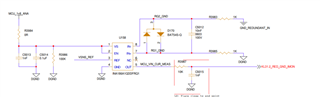


VCC = 1.76V
VSNS_REF = 0.256V 
Resistor R3987 10k disconnected
IN- shorted with IN+ between 7 and 8 pins.
In this setup I should get at output pin5  the input of VSNS_REF right? 
But I getting 0.222V that is lower of VFER = 0.256V! 

I think that it because of VCC is close to minimum 1.7V but not sure! 
Can u help me to clarify this issue pls, maybe there is other things that I don't know or don't see?

  • Hi Evgenykoc,

    Although we don't spec device electrical characteristics at a voltage below 1.8V, you shouldn't have an issue operating it close to the recommended minimum. Before we dig deeper into the issue, lets do a few sanity checks.

    Firstly, I'd recommend shorting the inputs with a simple wire/routing instead of the diodes - e.g. you could short across the capacitor.

    Second, ensure that your power source (1.76V) is stable and doesn't fall below 1.7V.

    Third, check your Vref voltage source, use a multimeter to ensure the voltage outputted is exactly 0.254V.

    Finally, probe the output at the pin of the device (if you haven't already) and check if output voltage is still less than Vref.

    If the above sanity checks pass, then please reply with scope shots of your supply voltage, Vref, Vout and IN+/- .

    Best,
    Mallika Senthil