This thread has been locked.

If you have a related question, please click the "Ask a related question" button in the top right corner. The newly created question will be automatically linked to this question.

TRF1305B1: PCB Differential input and output impedance details

Part Number: TRF1305B1
Other Parts Discussed in Thread: TRF1305

Tool/software:

HI,

When I am referring to the data sheet in PCB recommendation section.

the input and output to the IC is routed as Coplanar single ended 50 OHM, after resistor it has been routed as coplanar 100 OHM. 

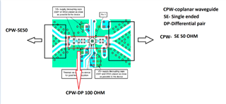
In my design input to the ic is from a photo diode which has PD+ and PD- signals.

Please clarify the following points:

whether it is Coplanar or Non coplanar. What is the impedance that should follow for routing.

  • Hi there,

    If you have differential signaling going all the way to the input to the TRF1305, you can use differential GCPW (grounded coplanar waveguide) of 100 ohms differential impedance the entire way, as shown on the EVM up to where it splits into two 50 ohm GCPW. You can also use other types of transmission lines, like microstrip or stripline, as long as the characteristic impedance is kept as 100 ohms differential.

    The reason why the EVM splits into 2 single ended transmission lines rather than just keeping it differential, is so that regular SMA connectors can be used to interface with the EVM.

    Thanks,
    Gideon