This thread has been locked.

If you have a related question, please click the "Ask a related question" button in the top right corner. The newly created question will be automatically linked to this question.

TLV3402: bipolar power supply and level translation

Part Number: TLV3402


Tool/software:

Hi, 

 we use TLV3402 in dual window comparator configuration for detection of overcurrent in both directions.
Comparator is powered in bipolar configuration +/-5V but output should swing between 0 and 3.3V. Voltage divider is implemented on the output as level translator.
The input signal for comparator is output of the difference amplifier. 

 We assume the voltage translation hasn't been implemented properly, but we want to share some observation. Actually, we need help to figure out, why this is happening here.
 

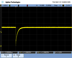
No current is flowing through the shunt resistor and TP507 is pulled to 3.3V. So, if we want to check voltage levels of test points TP507 and TP505 against GND using digital multimeter, we have observed short voltage drop on the TP507. 
We connected the oscilloscope probe tip first, and afterwards the digital multimeter in order to record the voltage drop. 
However, if we do the same on the TP505, nothing happens, or no voltage drop is present.  Actually, this drop on TP507 can be provoked if you shortly connect 1nF capacitor or 10Meg resistor, or any other strange body that has enough absolute self capacitance.  

If we add capacitor 1~10nF between TP507 and GND, no voltage drop can be observed anymore.

Please find attached schematic representation and waveform.

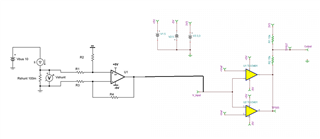
Could you help us to understand what is going on here and why?
How the level translation on the output could be improved?  


Regards

Josko


  • Hi Josko,

    What is generating the -5V? Can it handle 330uA? When the output goes low, the -5V has to sink the pull-up current.

    What is the -5V line doing at the same time? Is it getting yanked-up when the output goes low?

  • Hi Paul, 

    What is generating the -5V?

    The -5V rail comes form a TPS7A3001.

    Can it handle 330uA?

    I believe 330uA is negligible current for TPS7A3001DGN, which can give us 200mA because of small voltage drop. 
    It is powered from -6,5V inverting buck boost. 

    When the output goes low, the -5V has to sink the pull-up current.

    The problem here is not when the output goes low. This actually works. The real problem is that output can be forced low for a short period of time when the test point TP507 (the output of comparator after external pull up resistor) is measured by DMM or oscilloscope probe, while the input voltage of comparator is 0V or better to say within reference thresholds -Vref < Vin_comp <+Vref. 

    What is the -5V line doing at the same time?

    I haven't checked this but currently I am not able to perform this measurement. It will take same time to do this, 2~3 weeks.
    Maybe we will need to close this topic and re-open it later.   

    Is it getting yanked-up when the output goes low?

    It must be measured. 


    Regards

    Josko 

  • Hi Josko,

    Your level shifting is correct. I do not see a an issue there.

    If it is going low when touched with a captive load, then the "glitch" low is caused by the charging of the probe capacitance.

    Initially, a capacitor with no charge (Vc = 0V), looks like a short when power is first applied. So the cap initially pulls the output low when first touched, then  charges up to 3.3V through the 25k resistance. The comparator outputs are high-Z and have no effect.

    Your scope photo looks to take 5us to charge back to 99.3% (5 tau = 99.3%).

    tau = 5us/5 = 1us

    C = tau/R = 1us/25k = 40pF

    40pF is not too far off from scope probe capacitance (plus strays), and a little low for a DMM input (usually in the 100pF-200pF range).

    Finger capacitance can also range in the 50-500pF range depending on how hard you press and surface area touched. The larger caps will increase the tau.

    So if this is the case, then I do not see a problem. This is normal and explainable.

    If it seems to be too touchy, check and make sure the pull-up resistors are actually 15k and 25k. If they are 150k and 250k, then they will enhance the effect.

    https://en.wikipedia.org/wiki/Time_constant#Time_constants_in_electrical_circuits

  • Hi Paul, 

    thank you for elaboration. It sounds reasonable.  

    However, this behavior rises next concern, whether this output can be sensitive to strong electric fields?
    This behavior reminds me on some cases with RESET# of microprocessor if there was no capacitor between RESET# pin and ground. 
    Almost the same effect with scope probe or DMM could be observed.
    Later there was always a problem with ESD and EFT pulses that could reset uP.

    In your opinion, could strong electric field from ESD or EFT trigger comparator outputs to low shortly since they are high-z and produce the same effect as like as scope probe capacitance?  


    Regards

    Josko

  • Hi Josko,

    There is always that possibility...but if the fields are that strong, you are probably going to have other problems elsewhere.

    Here you were touching a (discharged) capacitance to an existing powered circuit. Unless you are "plugging" something in, that probably will not occur in normal operation.

    The stray capacitance, or added capacitor, will charge and discharge with the signal line levels. They will slightly exponentially "round" off the risetime when the logic transitions, but not randomly pull the line low like you are seeing.

    As for the RESET lines. Yes, if you just have the pull-up and do not have a capacitor, touching it with the scope probe will cause the same issue. If there is a capacitor, and it is large enough (say 10x the probe capacitance), then the fully charged capacitor will act as a charge reservoir and quickly charge the probe capacitance. So the glitch will be small or non-existent.

    It also could help to use lower value resistors to swamp out the stray capacitance (lower the node impedance so it is not as sensitive to the environment).

    t = RC, so making the capacitor smaller or making the resistor lower value shortens the "glitch" time.

    All this can be avoided with proper layout and keeping the traces short and shielded away from noise sources. Layout techniques is beyond the scope of this forum...that's a semester class.

  • Hi Paul, 

    Fine, I've understood. Thank you for the patience and profesional approach.  
    The topic can be marked as resolved.

    The background of the story is an issue in the field where we are getting false OC readings when inductive loads are turned on. 
    I've suggested to add 2,2nF capacitor between TP507 and GND at the output of comparator to see if this has anything to do with our observation with DMM or scope probe. 
      

    Regards

    Josko

  • Placing a cap there will slow down the rise and fall time, as now the cap has to charge and discharge through the resistors.

    It may stop a small, narrow glitch by delaying the rise time, but it also delays the reaction to actual over-current events.

    You may want to look at glitches/ground bounce on the supplies, particularly in the inputs to the amplifier as that is the most sensitive path.