This thread has been locked.

If you have a related question, please click the "Ask a related question" button in the top right corner. The newly created question will be automatically linked to this question.

INA826: Gain error if the IN- pin is shorted to negative power supply?

Part Number: INA826
Other Parts Discussed in Thread: INA122

Tool/software:

Hi all, 

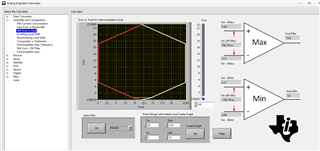
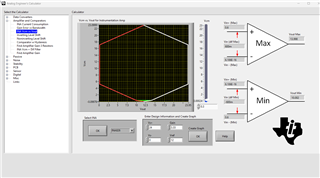
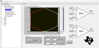
I am using INA826 in an application (some kind of low side current sensing) where the gain is set to 3.33 (hence 10/3), and the IN- pin is shorted to power supply minus. The positive power supply is 24V. The load on the output is 200K, and reference pin is on +12V (respect to negative power supply and IN- pins). I experineced the following: If I apply a low voltage to IN+ the gain is close to the designed 3.33 value (if the applied voltage to IN+ is less than 0.6V). If the voltage goes above this threshold the gain drops (the output is still monotonous, but the ration between out and in is not 3.33 anymore but somewhat lower). Why?  (the power supply is OK, the output is not heavily loaded). When I went through the datasheet I checked the sample circuits and found that IN- pin is always on a higher volatge than the negative power supply. It is a compulsory scenario for this instrumentation amplifier? 

Thanks, 

Janos

  • Hello Janos,

    A very helpful tool when working with instrumentation amps is the analog engineer's calculator: https://www.ti.com/tool/ANALOG-ENGINEER-CALC. This will help you generate the VCM vs VOUT plot for your application.

    Here is what is happening: when tying IN- to V-, you're setting one of the values in the common-mode voltage formula to a constant: VCM = (VIN+ - VIN-)/2. As you increase IN+ your common mode voltage increases by VIN+/2, but your input voltage differential is increasing by VIN+. Past a certain amount of input voltage, your input voltage differential will try to output a value larger than your linear output range. With 0.6V, your ideal output is VREF + 0.6V*3.33 = 13.998. However, your common-mode voltage is 0.3V. Putting the following values into the analog engineers calculator, you can see that your maximum Vout is 13.998.

    Now if we increase the input voltage slightly to 0.7V, we see that the input voltage differential is 0.7V, and the VCM is 0.35V. Now our ideal output is 14.331V, and our maximum output voltage with this range is 14.1V

    The reason IN- is generally tied to a value above V- is because the maximum output swing range is close to the center of the common-mode range. There are some specialized devices that can achieve a valid common-mode range near V-. INA122 has a level-shifted input (that is not well described in the analog engineer's calculator) that allows for input common-mode voltages near V-.

    Best,
    Gerasimos