This thread has been locked.

If you have a related question, please click the "Ask a related question" button in the top right corner. The newly created question will be automatically linked to this question.

OPA2187:High Side Current Measurement Error

Part Number: OPA2187
Other Parts Discussed in Thread: RES60A-Q1

Tool/software:

Hi,

Greetings!

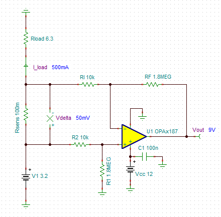
I’m Rohit Gupta, a Hardware Design Engineer at Applied Electro Magnetics Pvt. Ltd. We are currently using the OPA2187 operational amplifier for high-side current sensing. The measured current is 500 mA, and we're using a 0.1 Ω current sense resistor with a circuit gain of 180.

Based on our calculations, the expected output voltage is 9 V. However, we are observing an output of approximately 9.3 V. Could you please help us understand the reason for this discrepancy?

Additionally, could you clarify why the OPA2187 might not be suitable for high-side current sensing applications? Please note that the op-amp is powered with a single +12 V supply.

Thanks,

Rohit Gupta

  • Please show the schematic and the actual input voltages.

  • Hi Rohit, 

    Please provide the schematic as Clements suggested. It looks like that you are dealing with V-to-I converter. 

    Based on our calculations, the expected output voltage is 9 V. However, we are observing an output of approximately 9.3 V. Could you please help us understand the reason for this discrepancy?

    Here is the V-to-I reference design and it may help you to provide some ideas. 

    https://www.tij.co.jp/lit/ug/slau502/slau502.pdf?ts=1749125087254&ref_url=https%253A%252F%252Fwww.google.com%252F

    https://www.ti.com/lit/an/sboa437a/sboa437a.pdf?ts=1749077399205

    https://e2e.ti.com/support/amplifiers-group/amplifiers/f/amplifiers-forum/1515139/opa189-output-voltage-vo-swing-from-rail

    If you have other questions, please let me know. 

    Best,

    Raymond

  • Hi Raymond,

    Please Find the attached schematic diagram.

    Thanks,

    Rohit Gupta

  • Hi Rohit, 

    Based on our calculations, the expected output voltage is 9 V. However, we are observing an output of approximately 9.3 V. Could you please help us understand the reason for this discrepancy?

    100*0.3V/9V = 3.33% 

    The difference amplifier requires good resistor ratio matching in order to measure the voltage delta precisely. I do not know what resistor tolerance you selected, but this could be a part of an error. 

    say 1.8Mohm +/1% will give you +/-18kohm errors and difference could be up to 36kohm. So the 1.8Mohm/10kohm resistor matching will be a part of errors. So a small mismatching errors * 180V/V could be a significant errors. So my guess is that matching resistor is likely your major error source. 

    Your power rail of 12Vdc could generate an error. If you use noise switching 12Vdc power supply, the PSRR is unable to attenuate the noise ripple at the rail. the error could appear at the output stage of the difference amplifier. 

    The op amp's input offset error, Vios, though is small, but 180X will also contribute to a part of the total errors. 

    If your PCB or op amp has external leakage current, this will also contribute to the total errors due to 1.8Mohm resistor.  

    For radiometric precision resistor, you may consider to use RES60A-Q1 series.  

    https://www.ti.com/lit/ds/symlink/res60a-q1.pdf?ts=1749194524198&ref_url=https%253A%252F%252Fwww.ti.com%252Fproduct%252FRES60A-Q1

    Additionally, could you clarify why the OPA2187 might not be suitable for high-side current sensing applications? Please note that the op-amp is powered with a single +12 V supply.

    Please see the chopper application note. 

    https://www.ti.com/lit/wp/sboa586a/sboa586a.pdf?ts=1749191433770

    If you have other questions, please let me know. 

    Best,

    Raymond

  • Hi Raymond,

    Thank you for your response.

    However, I’d like to point out that we have used resistors with a 0.1% tolerance. The selection of this op-amp was primarily based on its low input offset voltage, minimal offset voltage drift, high CMRR, and high PSRR—factors we believed would ensure precision.

    Could you please help us understand how such a significant error could still occur with this IC?

    Thanks,
    Rohit Gupta

  • Hi Rohit, 

    Could you please help us understand how such a significant error could still occur with this IC?

    You have a high gain circuit, where the worst-case gain error is from resistor mismatching, even with 0.1% tolerance. Please try 0.01% tolerance or lower the gain. 

    Assume your input differential voltage of 50mV is exact (no error in Vdiff), resistor mismatch in the difference amplifier converts some of common mode voltage, Vcm into differential voltage error, which it gained by 180V/V. 

    If R2/R1 ≠ R4/R3, the Vcm at input will convert tje error into differential output voltage, where Vout_error = Gain*0.1%*Vcm.

    Your Vcm = 3.2V, and let us say you have gain errors of 0.1% --> Vou_error_max = 0.001*3.2*180 = 0.576V, which is the max. from your resistor mismatch, a dominated error source. You see 0.4V difference at the output, which is within the error range. 

    Try manual matching your resistor ratio down to approx. 0.01% by checking the ratio 1.8Mohm/10kohm down to 180V/V +/- 0.018V/V range, you may reduce the Vos error by a factor of 10 or ~9.04V instead (the manual matching R2/R1, R4/R3 are time consuming). 

    There are several other error sources in the high gain difference amplifier, but the mismatching R2/R1 ≠ R4/R3 is dominate error in the circuit. 

    Best,

    Raymond