


Tool/software:
Hi, I used an LM7171BIN op-amp to amplify my source, but it doesn’t seem to work.
I have a 150 ps laser pulse detected by a PDA10A2 (Thorlabs). A 5 MHz low-pass filter (Mini-Circuits SLP-5) is then connected to the photodiode to filter out high frequencies and only pass the lower 5 MHz components. This is then used as the input to the op-amp circuit for amplification.
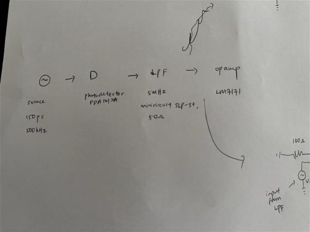

Setup


Op amp configuration #1

Op amp configuration #2
Most bottom row with orange wire = GND
2nd bottm row with white wire = +10V
3rd bottm row with black wire = -10V
Grey wire at left = input
Green wire at right = output
----
The op-amp is supplied with a ±10V power supply. Feedback resistor of 500ohm with another resistor at 100ohm. Hence expected gain is 6. I’ve already added a 0.1 µF ceramic capacitor and a 10 µF electrolytic capacitor for decoupling, connected between V+ to GND and V– to GND. I also added a 3.3 pF feedback capacitor to help stabilize it. I made sure the gain is > 2 (as the op-amp is only stable for gains above 2) and used a 500 Ω feedback resistor, as recommended in the datasheet. However, it doesn’t give me the expected output — an amplified version of the blue line. Instead, I get a sinusoidal waveform. I know this is a sign of the op-amp oscillating.

The blue line is the original input

This purple sine form is the output - shape is nowhere near to the input
I initially thought the issue might be the input signal (since much of the high-frequency energy was removed by the LPF), but when I replaced it with a pulse generator, there was still no amplification — which leads me to suspect the op-amp itself might be the problem.

Input signal from pulse generator

Output signal from op amp using pulse generator.
Can anyone help me?
Alternatively, I’m open to suggestions for a more suitable op-amp — one that’s not extremely high-speed or high GBW, since my signal is only in the MHz range and this current op-amp seems too sensitive and complicated to work with.
Thanks!
