This thread has been locked.

If you have a related question, please click the "Ask a related question" button in the top right corner. The newly created question will be automatically linked to this question.

INA851: Signal Conditioning Circuit with Buffer Amplifier

Part Number: INA851
Other Parts Discussed in Thread: TINA-TI

Tool/software:

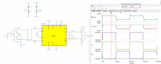
I am looking for a circuit to amplify ±0.2V differential from a full bridge transducer to ±5V balanced differential output into twisted pair cable. Bandwidth 0-20,000hz. The goal is a very small PCB wired inline on the transducer cable. Gain to be set by resistor on the INamp, output clamped at ±5V. Power input is flexible, maybe ±12VDC. Low-noise, high CMRR.

My thought is to use the INA851 with AD8139 (or similar) as a buffer amplifier to drive the cable capacitance (about 3nF, 30m of cable to the data acquisition). The cable would have 100Ω nominal impedance, instrumentation people usually do not terminate but they could if instructed.

Does INA851 + AD8139 make sense? Any thoughts on the circuit? How to keep component count down and the PCB small?

Thanks.

  • Hi Thomas,

    What are you planning to connect to the end of the cable for the data acquisition? I can only comment on the INA851 implementation as the AD8139 is a competitor device. I will check via simulation to check if the input sensor side is compatible with the INA851 and respond back to you in this thread. 

    Thank you!
    Regards,
    Ashley

  • I am happy to go with a TI full differential buffer amplfier that will do a good job driving ±5V into twisted pair, a suggestion is appreciated. The data acquisition input is an Opamp anti-aliasing filter. The sensor end is various full Wheatstone bridge accelerometers, 1000Ω to 2000Ω output impedance.

    I'm happy to eliminate the buffer amplifier if the INA851 can drive the cable. INA851Load Capacitance is 100pF (frequency unspecified) but I assume it can handle more capacitance at low frequency. These accelerometers have negligible output above 20khz, so if the INA851 can drive the cable capacitance (1.5nF if we use low capacitance cable) at 20khz the circuit can be simplified. That would be great, we want tiny boards.

    Fig. 7-44 shows 50Ω Riso stabilizing the amplier under capacitive load, is Riso between the differential outputs or in series on each?

  • Hi Thomas, 

    Could you provide the datasheet for the cable (both low capacitance and higher capacitance) that you are planning on using? My thinking is that if the sim results show that the INA851 by itself cannot drive the cable, we can add a line driver amplifier to the in between, specifically looking for one that is small-size optimized. 

    And yes, for the Riso implementation, you would need to add Riso resistors on series to each output pin. We can also add feedback capacitors to improve stability which I am working to simulate. 

    What is the input voltage range coming out of the wheatstone bridge? 

    Regards,
    Ashley

  • We have used Belden 8723 for years, also a link for Allied 1820, which has lower capacitance (15pF/ft). Typical output for the sensors is ±0.2V, so we need gain around 25, easy to achieve in the INA851. https://www.awcwire.com/product/1820

  • Hi Thomas, 

    Thanks for your patience as I work out the design feasibility. Using only the INA851 to drive the cable should work as long as you add an Riso in series connected to each output pin. I simulated this with 100ohms for Riso, but this value may need to be increased in the final design as it is difficult to fully simulate the electrical characteristics of the cable.

    You mentioned wanting an output of ±5V into the twisted cable, so in order to achieve this, you will need a front gain of 50, which means you would use a resistor or about 123ohms. You can verify your input/output conditions as well as the boundary plot using our excel calculator located on the product page: 

    Simulating this in TINA, you get a differential output voltage of about ±5V for an input signal of ±0.2V. Checking the AC response, there is minimal gain peaking, so the cable load conditions with the Riso of 100ohms should keep the INA851 stable. 

    I have also attached the TINA-TI simulation below for reference - please note that I used a VCLAMP in the simulation that matches the supplies as the model does not converge well when the output gets too close to the VCLAMP voltage. 

    INA851_sensor.TSC

    Please let me know if you have any questions.

    Thank you!
    Regards,
    Ashley

  • Thanks! You note the model does not converge well if output gets close to the VCLAMP voltage. Is this only an issue with teh simulator? Is it OK in practice to set VCLAMP only slightly higher than output voltage?

  • Hi Thomas, 

    Yes, the VCLAMP issue is only on the model. You can set VCLAMP to +/-5V or the desired clamp voltage as long as the clamp voltages are at least 3V apart and 1.5V from the Vs supply rails. The output voltage will swing approximately 600mV beyond the clamp voltage in order to reduce distortion effects, see section 8.3.5 in the datasheet. 

    Regards,
    Ashley

  • Thanks for all, you were extremely helpful., Tom