This thread has been locked.

If you have a related question, please click the "Ask a related question" button in the top right corner. The newly created question will be automatically linked to this question.

INA2332

Other Parts Discussed in Thread: INA2332, INA332

Hi


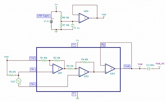
I am planning to have a USB powered Amplifier to connect to the PC Sound card.

Can I use the given circuit or I need to have some isolators(or different groun gplane or anything)?


Thanks for helping.

  • Hello Nikhila,

    The INA2332 is a dual instrumentation amplifier that can operate with a power supply from 2.7V to 5.5V.  Therefore you can power the device with the voltage from a USB connection.

    Concerning your schematic...can you please explain the purpose of the two 1kohm resistors?  Also, what is the relationship between GND and the ground symbol?

    Concerning isolation, why do you need to isolate between USB and a PC sound card?

  • Dear pete Seming,


    Sorry I am talking about INA2322. My apology for misleading you.


    Which require a +-2V(TYP) supply. So I thought of using this basic method to make a dual supply (IK resistors to act as a voltage divider).

    Inserting a cap to ground the high frequency is appreciated or it is it redundant?


    Isolation is required, since this is going to use as a physiological data acquisition and to avoid risk *(if persists).

     * My very basic doubt is If am not using an Isolator and making a +-2.5 V by grounding the resistor junction, and feeding back to the PC through soundcard, there could be any potential problem that will harm my mother boards?

    Hope you understand my problem!!!


  • Hi Nikhila,

    Pete is tending to another issue currently, so I will try to help.

    To start, this method will not successfully generate dual supplies for the INA2332.  Unless you choose to use the +5V USB supply to generate +/-2.5V supplies with a power converter, then the INA2332 should be single-supply powered from the USB +5V and GND.  Since your audio signal will be a bipolar signal, it will need to be biased to the mid-supply voltage of 2.5V before it is sent to the inputs of the amplifier so that the input common-mode range of the amplifier is not violated.  You can create the +2.5V reference using the same resistor divider previously shown, but this voltage must be buffered with an amplifier so any loading on the reference will not affect the reference voltage. 

    A very simple example of this type of circuit can be seen in the circuit and results below.  An option to AC couple the output of your amplifier is shown with the C2 capacitor.  The AC coupled output should reduce concerns regarding DC voltage potential differences between this output and your sound card's input.  I did not have a model for the INA332 so please beware that the model shown below was quickly created with ideal op-amps and the datasheet limitations of the INA332 will not be displayed in this model.  You must check on your own that the operating conditions of the INA332 are not being violated while performing simulations on this circuit. 


    7115.Ideal Schematic.TSC

     I am not going to comment on the need for isolation, this should be decided by yourself and the safety requirements of the application you're designing. 

    Thanks,
    Collin Wells


  • Thanks a lot for the mail.

    Could you please explain me " this method will not successfully generate dual supplies for the INA2332"   this.  Because I got + - 2.5 volt from USB +5 volt (please see the attachment ). You mean to say ,there could be 'fatal' problems?


    I need Isolation at this instance, Could you please suggest me the best suitable component for USB power isolation. I am in dark...Optocoupler worked finr on BB but not on PCB. Please help.

  • Hi Nikhila,

    Yes I understand that if you put the RTN/COM/GND on your multimeter to the mid-point between the two resistors you will read +/-2.5V.  This does not mean that you've successfully created dual supplies.  All of the current in your circuit must return to the USB GND signal.  In your case you're trying to return it to the mid-point of those two 1kOhm resistors, this is the fundamental issue.  

    I would strongly suggest that you operate the INA2332 single-supply from the USB +5V and GND and bias the input signal to mid-supply using the circuit shown in the previous post.  The buffer was included after the resistor divider because the REF input of the INA2332 must be driven with a low impedance source and the 1kOhm impedances will cause errors.    

    Regarding the USB isolation, I am not an expert in this subject and I would suggest you direct your isolation questions to the appropriate E2E forum such as one of the ones below:

    Isolated Controllers:
    http://e2e.ti.com/support/power_management/isolated_controllers/default.aspx

    Power Interface:
    http://e2e.ti.com/support/power_management/power_interface/default.aspx

     Best Regards,
    Collin Wells

  • Now I realised....Yes biasing of signal is the best choice.


    Thanks for te help.

    Love

    Nikhi