Part Number: INA230
Tool/software:
Hi,
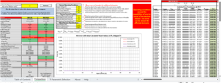
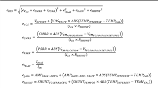
I'm trying to understand how to go about calculating
the worst cases error calculation in current sensing reading
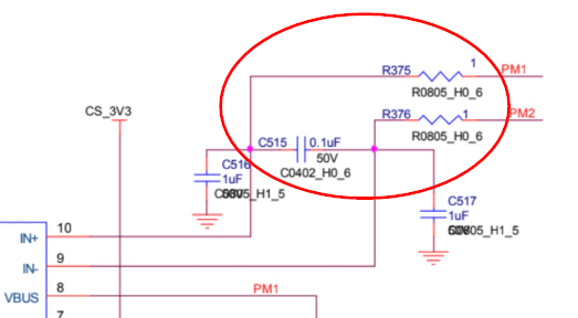
Here's the schematic:

Regards
Jonathan Kabangu,
Part Number: INA230
Tool/software:
Hi,
I'm trying to understand how to go about calculating
the worst cases error calculation in current sensing reading
Here's the schematic:
Regards
Jonathan Kabangu,