Part Number: TLV9002
Tool/software:
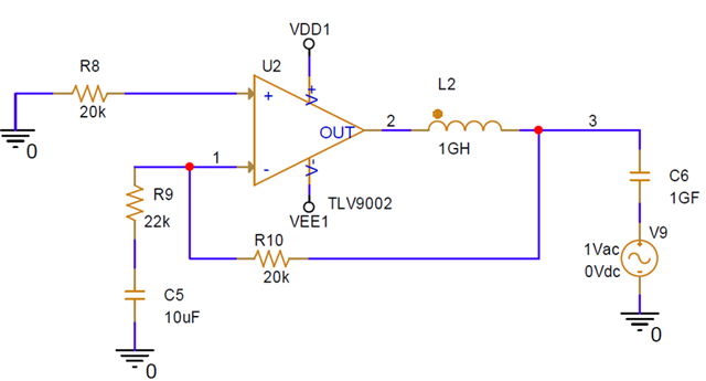
VDD1 = 3.3V, VEE1 = -3.3V
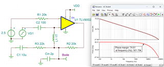
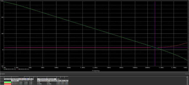
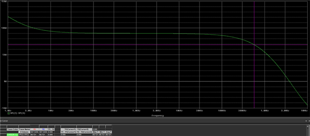
My simulation circuit and results are shown in the figures. The gain crossover frequency is approximately 560 kHz, and the corresponding phase shift of the loop gain is +68°. In this case, is the phase margin 112° or 248°?
If the phase shift of the loop gain is -68°, then what is the phase margin? 112° or ?
When analyzing the stability of an operational amplifier, what are the definitions and calculation formulas for phase margin and gain margin? Do these two parameters appear on the open-loop response curve or the loop gain response curve?
Thanks!