Tool/software:
Designing high-performance PWM DACs for field transmitters.pdf
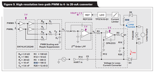
the simulation results of the Voltage to Loop-Current Converter circuits in the Figure 9 is not match the Equation 19.
Tool/software:
Designing high-performance PWM DACs for field transmitters.pdf
the simulation results of the Voltage to Loop-Current Converter circuits in the Figure 9 is not match the Equation 19.