This thread has been locked.

If you have a related question, please click the "Ask a related question" button in the top right corner. The newly created question will be automatically linked to this question.

XTR300: XTR300 Power Consumption

Part Number: XTR300
Other Parts Discussed in Thread: , XTR305

Tool/software:

Hi,

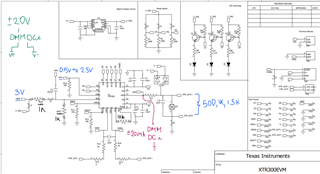
I use XTR300 in my design and make it work in current mode. I provide it with a supply voltage of ±20V. I may need it to provide a maximum current output of ±20mA, and the load resistance may be 1KΩ. I want to know how much current it needs at least to make it work properly? My DC-DC module can provide a maximum current of ±42mA. Is this enough?

Best,

Junzhe

  • Hello Junzhe, 

    I expect that to be enough overhead for the current consumption of the device, but I can double check in lab for you. I will reply to this thread with my current consumption in the next few days. 

    All the best,
    Carolina

  • Hi Caro,

    Thanks a lot for your help! I will wait for your feedback. In my previous test, I think ±42mA can work. But I still want the precise result to make sure everything works well.

    Best,

    Junzhe

  • Hello Junzhe, 

    I tested this on the XTR300EVM, the schematic can be found in this thread: (+) XTR300EVM: Schematics - Amplifiers forum - Amplifiers - TI E2E support forums

    As you can see, the positive power supply (V+) drives a 5V reference voltage (TPS7A1650) - this may be a contributor to power consumption. I took two measurements, one in which the 5V reference is used on the EVM & one in which I provide the 5V externally - not much difference in the results. 

    All current consumption is within your DC/DC limitation of ±42mA: 

    (Please note that the input is not a precision DC source, therefore the output current is a little off)

    Driving internal reference from V+ (5V)

    Input (V) Output (mA) Consumption from 20V (mA) Consumption from -20V (mA)
    0 -20.02 -3.74 23.22
    1 -11.69 -3.29 13.9
    2 -3.57 -2.84 5.44
    3 4.46 -7.5 1.76
    4 12.93 -16.55 1.79
    5 20.68 -24.75 1.83

    External reference (5V)

    Input (V) Output (mA) Consumption from 20V (mA) Consumption from -20V (mA)
    0 -20.02 -1.72 23.67
    1 -11.53 -1.68 14.27
    2 -3.87 -1.65 5.79
    3 4.62 -7.07 1.74
    4 12.36 -15.46 1.76
    5 20.38 -24.44 1.81

    All the best,
    Carolina 

  • Hi Carolina,

    Thank you very much for your answer and test results. I would also like to know if the current required from the power supply will change when the XTR300 drives loads of different value with the same current?

    I also want to know the maximum output capacity of the XTR300, because when I tested it before, my load was 1KΩ, and I provided the XTR300 with a ±20V power supply to make it output ±16mA. According to Ohm's law, does this mean that the maximum current that the XTR300 can provide under ±20V for a 1KΩ load is ±20mA?

    Best,

    Junzhe

  • Hello Junzhe, 

    Here is my configuration for the testing I completed. 

    The output current has not much to do with the load, it is set by RSET and ROS: 

    What different load resistors were you thinking of using?

    All the best,
    Carolina 

  • Hi Carolina,

    My Vref is 3V, RSET and ROS are 1KΩ, I get different outputs by changing the value of Vin.

    I plan to use the XTR300 as part of my medical stimulator. 1KΩ is the resistance value I use for testing(close to the tissue resistance value), but in real applications, the parameters of the object being stimulated are unknown(may also contain capacitance). I want to make my instrumentation can generate current range as wide as possible.

    Best,

    Junzhe

  • Hello Junzhe, 

    Interesting medical application :) Do you think the following test would be helpful? 

    Or do you think 50% resistance variation is too large? Would 900, 1k, 1.1k be better?

    All the best,
    Carolina

  • Hi Carolina,

    In my previous test, I think when the load value is below 1K(pure resistance), the system can work well, but when the load larger than 1K, the current may not enough due to the limitation of the supply voltage. In addition, I am curious when the  load is not pure resistance, what the output current will be like. Because the load at this time will become an RC network.

    In my previous tests, I connected an oscilloscope in parallel across the load, so I got the voltage between the load. I then use this voltage value to calculate the current value applied to the load and compare it with my expected value to ensure it is correct. And the current waveform I needed was a square wave, with a single pulse lasting about 100us, which meant it was difficult for me to observe the current waveform directly.

    I used Tina software to simulate, and you can see that the direct output Iout of the DRV pin is the ±20mA current I want, but after passing through R10 and C1, the current measured by AM1 begins to become irregular. At this time my load is pure resistance. I don't know if this means that my load can receive the current I need?

    In the data sheet, the role of R10 and C1 is mainly to protect the circuit, so I deleted them and directly connected the DRV pin to my new RC load, and I can see that the current signal of Iout is also ±20mA. This makes me a little confused.

    I have attached my simulation file so that you can help me verify it. Thank you very much for your help.

    XTR300 Square Wave (2).TSC

    Best,

    Junzhe

  • Hello Junzhe, 

    Understood, I ran a few simulations and am receiving some weird/inconsistent results. I think it would be best to proceed forward with test measurements. 

    I recommend implementing a current measurement with a DMM in series with the load (to measure the current).

    If you would like I can take this testing, could you tell me more about the square wave input, are these accurate rise and fall times?

    All the best,
    Carolina

  • Hi Carolina,

    The input signal I set in Tina is for testing purposes. The input square wave I actually used was generated by a DAC. 

    I have attached a picture, please ignore the parameters and just focus on its shape.

    Its rise and fall times are approximately 5us, and each half cycle lasts for 100us.

    I don't think a DMM is a good way to measure current because the rate of change is too fast to capture useful information. I don't have any device in my lab that can accurately measure current. So I have been using an oscilloscope to measure the voltage and then calculate the current.

    Best,

    Junzhe

  • Hi Junzhe, 

    Thank you for the details on the input source, I will respond back to this thread when I have measurement results. 

    All the best,
    Carolina

  • Hello Junzhe, 

    I think the XTR300 is incompatible with your test conditions. 

    Incompatibility 1: 

    The op amp that drives the current out of the device can only output the following voltage relative to the rail, (V−) + 3 to (V+) − 3, which is ±17V. 
    With a load of 1kohm, the most current across the load will be ±17mA. 

    The following table summarizes different resistive loads and maximum obtainable voltage across the load - these are derived using ohms law. 

    Rload Current across load
    1.2k ±14mA
    1.1k ±15mA
    1k ±17mA
    900 ±18.8mA
    820 ±20.7mA
    680 ±25mA

    I am not sure how in my earlier measurements I was able to get ±20mA. Likely is that at DC, the min/max in the datasheet can be stretched but at any frequency the following limitations is very clear. 

    Incompatibility 2: 

    In current output mode, the device can only output 1.3mA/us: 

    The input in your application is very steep, the rising and falling edges are 5us. This 5us allows 6.5mA to rise/fall in that time period. The target current differential of ±20mA is 40mA. Therefore, the rising and falling edges would have to be at least 30.7us to allow enough time for the XTR to keep up. 

    In my testing, my function generator only allows max 1 us edge - so its a bit more extreme but here are the results (across 680ohm): 

    Notice how the output (blue) does not get to the expected ±13.6V to achieve ±20mA. 

    If I increase the pulse width substantially (100us to 2.2ms), the device has enough time to eventually rise up to ~ ±13V (~±19mA): 

    Here is the power consumption in such scenario, i2 is 20V power supply & i3 is -20V power supply:


    Here is an example with a very slow sine wave input (notice how the device is almost at the full voltage) ~13.2V (±19.4mA)

    Here is the power consumption in such scenario, i2 is 20V power supply & i3 is -20V power supply. 

    Notice how both scenarios the power consumption is within the DC-DC converter limitation. 

    All the best,
    Carolina

  • Hi Carolina,

    Thanks a lot for your result. I would like to ask:

    1. What is the yellow waveform in your result?

    2. For your second picture. If the slew rate is 1.3mA/us for XTR300. ±19mA should be reach in 30us. But it use 2.2ms in your result which I think is strange, almost 70 times large. 

    3. For the current output mode of the XTR300, do I just need to make sure that I reserve enough time to meet the slew rate of its current change and that the product of the required maximum current and load value (I*R) is less than the supply voltage minus 3? So that I can apply the current I want to loads of different values? 

    But I don't understand why for a purely resistive load, when the output current remains unchanged, the required rise time will also increase when the resistance value increases.

    Best,

    Junzhe

  • Hi Junzhe, 

    Carolina is out today, so I will try to help in her place. 

    1. What is the yellow waveform in your result?

    The yellow waveform is the input step pulse into the XTR. Blue is output. 

    2. For your second picture. If the slew rate is 1.3mA/us for XTR300. ±19mA should be reach in 30us. But it use 2.2ms in your result which I think is strange, almost 70 times large. 

    Please note that the slew rate of 1.3mA/us is without the condition of a capacitive load, so with additional loads, the slew rate will decrease. 

    3. For the current output mode of the XTR300, do I just need to make sure that I reserve enough time to meet the slew rate of its current change and that the product of the required maximum current and load value (I*R) is less than the supply voltage minus 3? So that I can apply the current I want to loads of different values? 

    Yes, you need to have enough headroom so the device is not slew limited for the different load conditions. 

    But I don't understand why for a purely resistive load, when the output current remains unchanged, the required rise time will also increase when the resistance value increases.

    Could you clarify if you need the RC filter on the output or if the resistor in series (R10) can be removed for your application? I noticed you had it removed in your simulation drawing. 

    Regards,
    Ashley

  • Hi Ashley,

    Thank you for your help. For Q2, I don't think Carolina use capacitive load, she only use 680ohm resistor I think, so I don't think it should need such a long rise time. For Q3, I am not trying to use RC filtering at the output, my RC part is used to simulate real tissue-electrode impedance in simulation. In the data sheet, the role of R10 and C1 is mainly to protect the circuit, so I deleted them.

    I find some paper, which also used current stimulate. It can be seen that the current waveform is relatively regular, but the voltage waveform has a longer rise time. In my testing I have always measured the voltage waveform, so I have been confused about the rise time. But the current I want is already applied. I don't know if this understanding is correct.


    Best,

    Junzhe

  • Hello Junzhe, 

    Sorry for my delay in response, in my testing the device has a 10nF load. I can continue to recreate tests, but I simply do not think the XTR300 is a good fit for this application. 

    Out of the integrated device solutions, the only bidirectional current outputs are XTR300 & XTR305 - however these devices cannot support the large slew rate requirement and the expected load of ~1kohm for the output of ±20mA. 

    Instead, I recommend building a discrete solution Howland Current Pump, here are some resources: 

    If you require further assistance with discrete implementation - please make a new thread and reference to this one so the engineer may have context. 

    Thank you & sorry I couldn't make the XTR300 fit into your application. 

    All the best,
    Carolina