This thread has been locked.

If you have a related question, please click the "Ask a related question" button in the top right corner. The newly created question will be automatically linked to this question.

XTR116: XTR116 – Output Current Increases Over Time / Thermal Effect on External Transis

Part Number: XTR116

Tool/software:

Dear TI Support Team,

Hello,

I apologize for the delay in getting back to you and truly appreciate your helpful response.

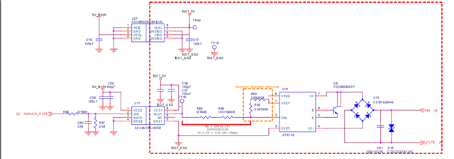
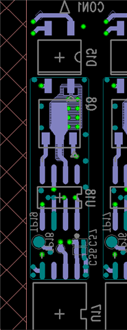
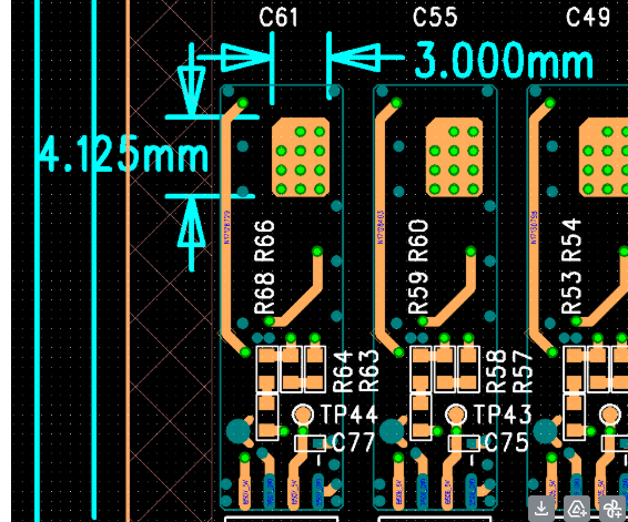
It seems my design files were not attached in the previous message, so I’ve now included both the PCB layout and schematic for your reference.

I would be grateful if you could review the following points and share your insights:

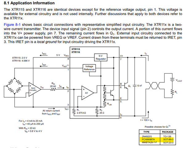
  1. I have reviewed the datasheet and am currently using the recommended FCX690BTA (SOT-89-3) transistor.

    • Is this package sufficient to handle the thermal dissipation in my design?

    • If so, could you recommend a specific TR that is more suitable in this package type?

    • If not, would you suggest switching to a different package?

  2. How much should I increase the copper area in order to improve the thermal performance in this situation?

  3. If there are any improvements you can suggest on the circuit design itself, I would greatly appreciate your feedback.

Thank you once again for your support. I look forward to your expert advice.

Best regards,

0. Dataheet
1.Circuit
2. PCB 
  • Hello Rakyoung,

    Your post is talking about previous messages, but I could not find any other posts by your account. Could you please include any other conversations so I may know what other details were shared?

    If this is not possible, could you please provide the following information.

    1. What is the value of VB+?
    2. What is the maximum current out of your Q8 transistor? I'm assuming it will be 4.3V*100/10k (43mA), since this is the maximum output of ADUM4195 with a 5V supply.

    If you are trying to implement the reverse voltage protection like figure 7-2, D16 and C61 should be on the other side of the voltage rectifier (D15). They should be connected between Pin 7 and Pin 4 of the XTR116.

    For the power dissipation of the FCX690B, please see the below highlighted thermal characteristics. The transistor can dissipate 1W continuously with a 15mm x 15mm x 0.6mm  PCB with a 1oz copper pour in still air, and 2W continuously with a 40mm x 40mm x 1.6mm PCB. With 43mA of output current, your maximum supply voltage that will

    Best,
    Gerasimos