This thread has been locked.

If you have a related question, please click the "Ask a related question" button in the top right corner. The newly created question will be automatically linked to this question.

THP210: LM35 and THP210 Combination

Part Number: THP210
Other Parts Discussed in Thread: LM35

Tool/software:

Hi All,

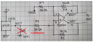
I have inherited a set-up for reading ambient temperature that goes as follows: LM35--> THP210 (gain 0f 1)--->Differential ADC.

For values of components please see the attached circuit.


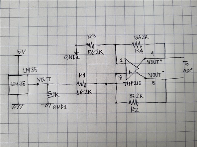
The problem: at room temperature I should get 230mV (the sensor 23 degree C environment), and I am getting that voltage at the output of the LM35. But the issue is that voltage keep increasing, in a 10 min interval I saw the output of the LM35 go from 230mV to 270mV.

Can anybody shade any light to why this is happening (the output keeps drifting up)?

Thank you.

  • Hi Roy, 

    the issue is that voltage keep increasing, in a 10 min interval I saw the output of the LM35 go from 230mV to 270mV.

    LM35 is a temperature sensor with 10mV/C slope. At 23C, it reads 230mV. At 27C, it reads 270mV. This implies that it increased 4C in 10 mins due to self heating likely.

    So remove the 1kohm load or increase 1kohm to >100kohm load.  

    Can anybody shade any light to why this is happening (the output keeps drifting up)?

    I assume that the temperature change is occurred at Vout of the LM35 sensor. Please make sure that 5Vdc to the LM35 is decoupled properly as well. 

    or place a LPF after LM35's Vout. 

    Please let me know if this helps. If this is LM35's issue, the product is supported by Sensing-THS team. I can transfer you there, if you'd like. 

    If you have  other questions, please let me know. 

    Best,

    Raymond

  • Raymond, 
    Thanks for your prompt answer. The self heating of the IC stops if the value of the resistor to ground is increased as you suggested (increasing it to just 2k helped). But there is a problem with this design, and that is the current from VOUT- pin of the THP is pumped back towards to LM35, through the resistor to ground, as a result there will drop across that resistor, and if this voltage is higher than the voltage generated by the LM35 then current will flow into LM35. 

    I have decided to simplify the design though, I am removing the THP210 and adding an opamp (gain=3) between the LM35 and ADC (single ended).