This thread has been locked.

If you have a related question, please click the "Ask a related question" button in the top right corner. The newly created question will be automatically linked to this question.

INA241A: INA241A or INA296A, which one to use for class-D audio amplifier TPA3255 and TAS5634?

Part Number: INA241A
Other Parts Discussed in Thread: TPA3255, TAS5634, INA253

Tool/software:

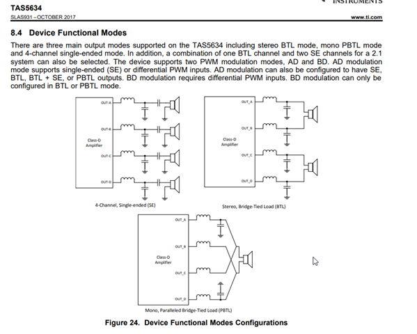
We would like to evaluate TPA3255 or TAS5634 to drive a DC voice coil motor, and inline current measure is selected. For TAS5634, PWM frequency is set to 500KHz. Which difference amplifier should I use for inline measurement use TPA3255 or TAS5634? Do I need PWM rejection for such class-D audio amplifier?

  • Hello Benyuan,

    Where would you be placing the Rshunt?  Would it be after the inductor from the image below?  I think it would be recommended as the frequency of the PWM is too high for the INA241, see attached snippet of datasheet.  I would recommend the INA296 and after the inductor.  The reason for the INA296 is it has the high bandwidth and does not have the enhanced PWM rejection.  If you want to place the Rshunt before the inductor I do not believe either of these devices will work due the the CMRR at high frequency for these devices.  At the moment these are the best that we have.

  • Thank you. We are using BTL or PBTL mode, where the speaker is replaced by a coil motor. so it is recommended that I place RShunt after LC filter for better noise immunity?

    BTW, we are facing the noise problem using discrete MOS as class-D driver, may be it is related, see the post below

    https://e2e.ti.com/support/amplifiers-group/amplifiers/f/amplifiers-forum/1528482/why-the-current-noise-variance-is-different-when-inline-sensing-h-bridge-current-in-forward-and-reverse-mode

    The difference is that we are using INA253 instead, the current noise is extreme large if we drive current from left half bridge to the right, and the VCM on INA253 is large, frequency is 500KHz, and not separated by 3us interval. In this situation, how could we still being able to measure the current at 500KHz PWM? is add a LC filter at the SW point of each half bridge helpful?

    Thanks!

  • Hello Benyuan,

    If you place the Rshunt after the LC filter it will be much better as the Voltage will not be changing as much as the switching frequency.  This switching frequency is what will impact the CMRR and have very high frequency components.  If you place it after the inductor the voltage transitions does not happen at the Rshunt.

    For the other post it seems like one direction the voltage changes (VCM) at the Rshunt more than the other do to the inductor(aka the motor).  I will tell my Holly about this.

    Also I am off tomorrow so replies will be delayed.

    Regards,

    Javier