Other Parts Discussed in Thread: OPA196, OPA182, XTR111, XTR105, XTR117, XTR116
Tool/software:
Hi,
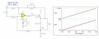
I have designed a circuit to generate a 4–20 mA analog output using PWM. The circuit functions correctly when the output current is calibrated (Zero: 4.00 mA, Span: 20.00 mA) by adjusting the PWM duty cycle at 1 kHz, using a digital multimeter (DMM) connected directly to the output.
However, we are observing a problem when the output is terminated with a 235 Ω load resistor to ground. In this case, the current increases beyond the calibrated value — for example, the duty cycle corresponding to 4.00 mA (as measured during calibration with a DMM) results in approximately 4.12 mA. This discrepancy becomes larger as the duty cycle — and therefore the output current — increases.
for example using 235ohm load resistor generates:
4.00mA --- 4.13mA
5.60mA --- 5.78mA
8.00mA --- 8.26mA
12.00mA --- 12.39mA
16.00mA --- 16.52mA
20.00mA --- 20.66mA
The difference also changes proportionally if we decrease or increase the load resistor.
D14 : schotkey diode PMEG3010BEA

However, the desired behaviour is to generate linear 4-20mA output, irrespective of change in load resistor. This output is to be used on different customer installations, where we expect the load resistor value in the range of 50 ohm to 500 ohm.
Hoping anyone from E2E forum or TI can help.
Thank you,