Other Parts Discussed in Thread: OPA859, TLV7011
Tool/software:
Dear Team,
the common mode range as shown below.Does that mean I can provide only upto 1.9V when operationg from 3.3V rail.

Regards
HARI
This thread has been locked.
If you have a related question, please click the "Ask a related question" button in the top right corner. The newly created question will be automatically linked to this question.
Hi Clemens,
Thank you very much.
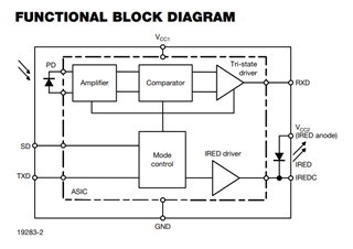
Actually I am implementing discrete IrDA receiver.In my earlier board I used an IC from Analog devices.It is not automotive qualified.So decided to go with discrete implementation.Below is the block diagram of the IC.

In the receiver section you can see that a trans-impedance amplifier + BPF + Comparator.
In my circuit I am using TIA + Comparator.I am using this opamp (OPA859-Q1) for my application.I use this opamp for TIA.
Why I used this high bandwidth opamp,the reason is given below.
The data rate of IrDA is 115.2 Kbps
Bandwidth≥3×Data Rate So for 115.2 kbps:Minimum Bandwidth≈3×115.2 kHz=345.6 kHz.
I considered 1 MHz (for margin and signal integrity).
The output of TIA is connected to a comparator and the comparator output will be connected to the microcontroller.
I asked this discrete implementation question in many forums.Did not get any response.
May I know your thoughts.
Regards
Thank you
In that case what will be the pass band frequency.
Also I found some other transceivers without BPF

Hello Hari,
Here is some feedback on our end as well:
Current source: Analog current source from an IR LED? If so, then:
Useful Collateral:
Let us know how your experiment goes.
Thanks!
Sima
Hi Sima,
Thank you very much.
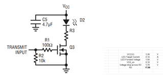
This is my IR LED. Below is the IR LED Circuit.

This is my photodiode.
The input capacitance of the diode is taken from the datasheet for the particular reverse bias.This diode capacitance is small.
Regards
HARI
Hello Hari,
Thank you for the update, I am glad it worked out!
Best Regards,
Sima